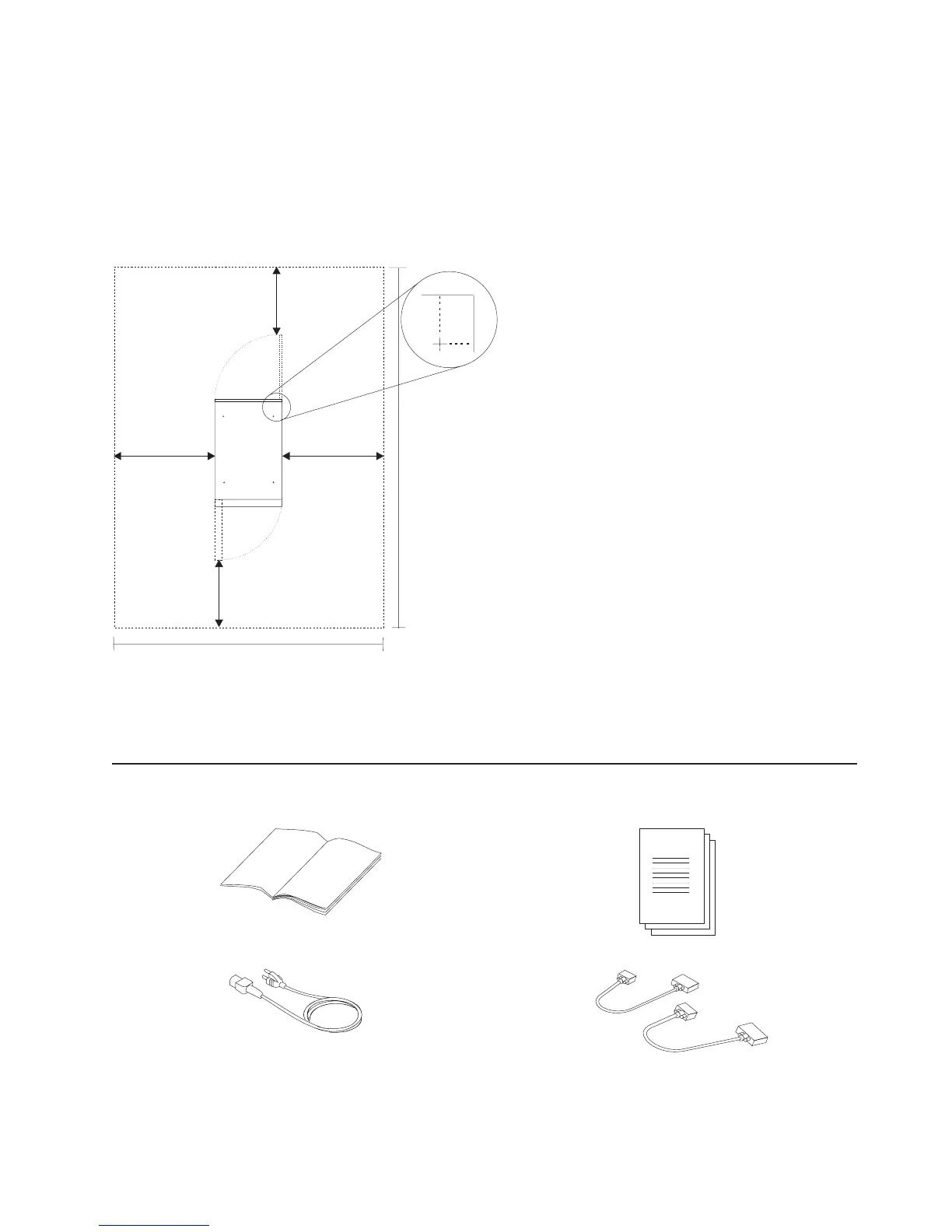
System Service Clearances
The following illustration shows the minimum space required. The amount of space needed by the units
during service is indicated by the dotted line in the illustration figure.
For multiple racks placed side by side, the left and right clearances apply only to the leftmost and
rightmost rack.
Rack Configuration
2474 mm (97.4 in.)
3564 mm
(141 in.)
915 mm
(36 in.)
915 mm
(36 in.)
610 mm (24 in.)
610 mm (24 in.)
Front
Caster
Location
(4.8)121
(3.1)
80
Note: Rack units are large and heavy and are not easily moved. Because maintenance activities require
access at both the front and back, allow for extra room. The footprint shows the radius of the
swinging doors on the rack.
Model 6C4 Rack Installation Inventory
h Books, CD-ROM and Other Media h ″About Your Machine″ Document
h Power Cables (1 standard, 2 optional) h 9-Pin to 25-Pin Serial Converters (2) (optional)
Appendix D. Setting Up the System 563
 Loading...


