Chapter 12. Fault and Attention LEDs
The system’s fault and attention LEDs can assist you in identifying failing components in your system.
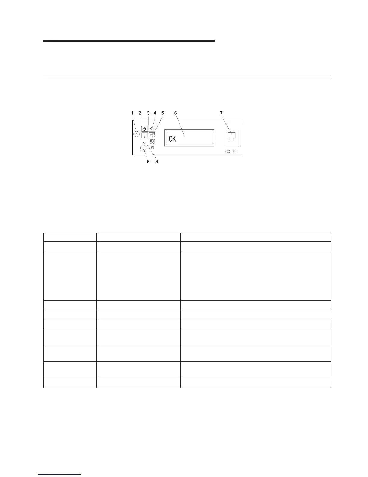
Operator Panel Display
If a failing component is detected in your system, an amber-colored attention LED is turned on solid (not
blinking).
1 Power-On Button 6 Operator Panel Display
2 Power LED 7 (FS1) Front Serial Connector
(RJ-48 Connector)
3 Attention LED 8 Service Processor Reset Switch
(Pinhole)
4 SCSI Port Activity 9 System Reset Button
5 Ethernet Port Activity
Number Component Name Component Description
1 Power-On Button Turns the system power on and off.
2 Power LED Blinking - When connected to the power source (System is
in standby mode).
Solid - When power-on button has been pressed.
Note: There is approximately a 30-second transition period
from the time the power-on button is pressed until the power
on LED goes from blinking to on solid. During the transition
period, you may observe the blinking intervals accelerate.
3 Attention LED Normal State - LED is off.
4 SCSI Port Activity Normal State - LED is on when there is SCSI activity.
5 Ethernet Port Activity Normal State - LED is on when there is Ethernet activity.
6 Operator Panel Display Displays current status of system startup, or diagnostic
information in the event of a hardware problem.
7 Front Serial Connector (FS1) Serial port uses RJ-48 connector. Use to plug in external
devices at the front of the system unit.
8 Service Processor Reset Switch
(Pinhole)
Service Personnel Use
9 System Reset Button Resets the system
543
 Loading...


