9. Place the adapter, component-side up, on a flat, static-protective surface.
10. Set any jumpers or switches as instructed by the adapter’s manufacturer.
11. Carefully grasp the adapter by its top edge, and align the adapter with the expansion slot and its
connector on the PCI riser card.
12. Press the adapter firmly into its connector.
Attention: When you install an adapter into the system, be sure that it is completely and correctly
seated in its connector located on the PCI riser card. Inserting and seating the adapter
card improperly might cause damage to the PCI riser card or the adapter.
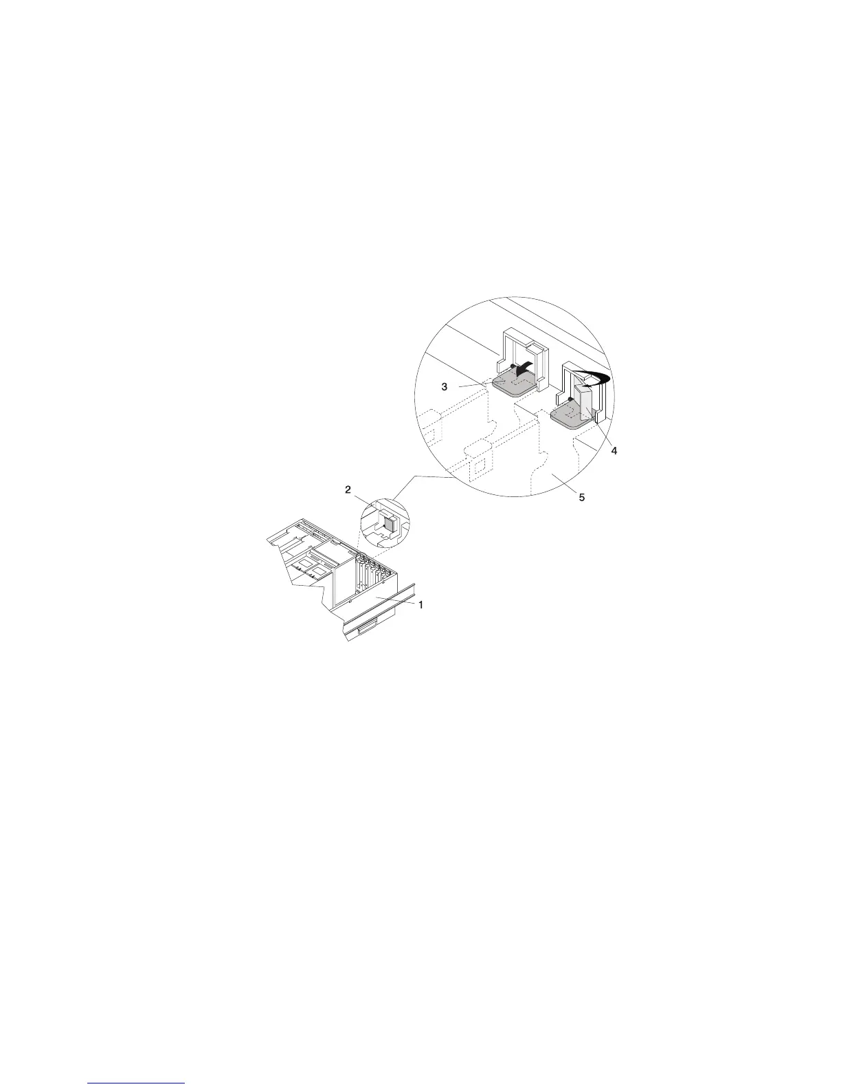
13. Lower the tab onto the PCI adapter EMC shield/connector faceplate. Rotate the adapter retainer clip
clockwise until it covers the tab at approximately a 45-degree angle. See the following illustration.
1 System Unit
2 Adapter Retainer Assembly (in the unlocked position)
3 Adapter Retainer Assembly (retainer seat down and the retainer clip in the unlocked position)
4 Adapter Retainer Assembly (retainer seat down and the retainer clip in the locked position)
5 PCI adapter face plate (dotted lines)
14. Replace the service access cover as described in “Service Access Cover Replacement (Model 6C4)”
on page 431 or “Service Access Cover Replacement (Model 6E4)” on page 437.
15. If you are servicing a Model 6C4, push the system drawer back into the operating position as
described in “Returning the Model 6C4 to the Operating Position” on page 430.
16. Connect the adapter cables.
17. Reconnect the power source to the system.
18. If you are servicing a Model 6C4, route the cables through the cable-management arm.
19. Go to ″MAP 0410: Repair Checkout″ in RS/6000 Eserver pSeries Diagnostic Information for Multiple
Bus Systems. If necessary, refer to “Starting the System without an HMC Attached” on page 425.
After you have completed checking the system, close the rack or system doors.
Chapter 9. Removal and Replacement Procedures 449
 Loading...


