66 IBM System x3850 X6 and x3950 X6 Planning and Implementation Guide
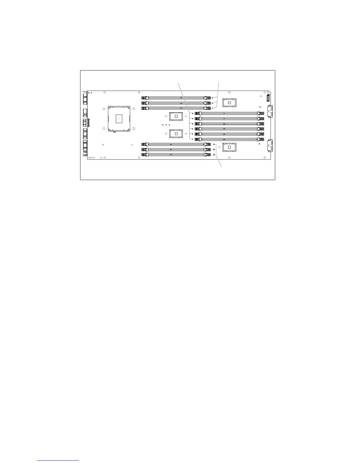
The system board of the Compute Book also contains a set of error LEDs for each memory
module, which show failed modules when the light path diagnostic button is pressed.
Figure 3-14 shows a diagram with DIMM error LEDs of the Compute Book’s left side.
Figure 3-14 DIMM error LEDs placed on the left side of the system board
3.6.2 Compute Book population order
The x3850 X6 server supports these combinations:
2 Compute Books
4 Compute Books
A configuration of 3 Compute Books is not supported. A configuration of one processor is only
supported in model 3837-A4x. No other server model or CTO configuration supports one
processor.
The x3950 X6 supports these combinations:
4 Compute Books
6 Compute Books
8 Compute Books
Other combinations are not supported.
(Left side of board)
DIMM 1 - 3
error LEDs
DIMM 7 - 12
error LEDs
DIMM 4 - 6
error LEDs
 Loading...