1-2
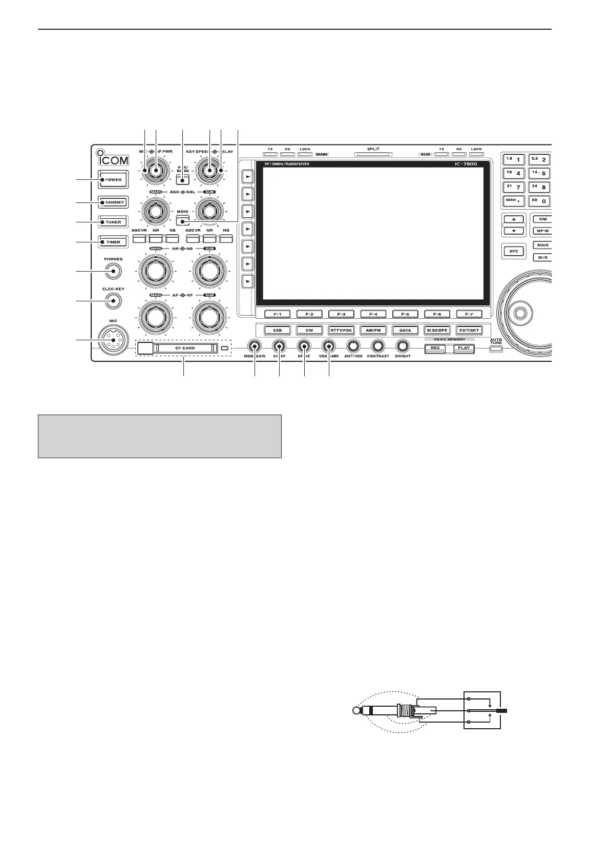
■ Front panel
q POWER SWITCH [POWER] (p. 3-2)
➥ Push to turn the transceiver power ON.
•The [POWER] indicator above this switch lights
green when powered ON.
➥ Hold down for 1 second to turn the transceiver
power OFF.
•The[POWER]indicatorlightsorangewhenthetrans-
ceiver is OFF when the internal power supply is
switched ON.
w TRANSMIT SWITCH [TRANSMIT]
Selects transmitting or receiving.
•The[TX]indicatorlightsredwhiletransmittingandthe
[RX] indicator lights green when the squelch is open.
e ANTENNA TUNER SWITCH [TUNER] (p. 10-5)
➥ Turns the internal antenna tuner ON or OFF (by-
pass) when pushed momentarily.
•The[TUNER]indicatorabovethisswitchlightsgreen
when the tuner is turned ON, goes off when tuner is
turned OFF (bypassed).
➥ Tunes the antenna tuner manually when held
down for 1 second.
•The[TUNER]indicatorblinksredduringmanualtun-
ing.
•Whenthetunercannottunetheantenna,thetuning
circuit is bypassed automatically after 20 seconds.
r TIMER SWITCH [TIMER] (p. 11-4)
➥ Turns the sleep or daily timer function ON or
OFF.
•The[TIMER]indicatorabovethisswitchlightsgreen
when the timer is in use.
➥ Enters timer set mode when held down for 1 sec-
ond.
t HEADPHONE JACK [PHONES]
Accepts standard stereo headphones.
•Outputpower:50mWwithan8Ω load.
•Whenheadphonesareconnected,theinternalspeaker
or connected external speaker does not function.
y
ELECTRONIC KEYER JACK [ELEC-KEY] (p. 2-4)
Accepts a paddle to activate the internal electronic
keyer for CW operation.
•Youcan select internalelectronickeyer, bug-keyor
straight key operation in keyer set mode. (p. 4-12)
•Astraightkeyjackislocatedontherearpanel.See
[KEY] on p. 1-13.
•Keyerpolarity(dotanddash)canbereversedinkeyer
set mode. (p. 4-12)
•4-channelmemorykeyerisavailableforyourconve-
nience. (p. 4-8)
u MICROPHONE CONNECTOR [MIC]
Accepts an optional microphone.
•Seep.15-4forappropriatemicrophones.
•Seep.2-10formicrophoneconnectorinformation.
1
PANEL DESCRIPTION
Turn the internal power supply ON in advance. The
internal power supply switch is located on the rear
panel. (p. 3-2)
 Loading...