4-6
D APF (Audio Peak Filter) operation
[DIGI-SEL]
(SUB)
[DIGI-SEL]
(MAIN)
[APF/TPF]
(MAIN)
[APF/TPF]
(SUB)
The APF changes the audio frequency response by
boosting a particular frequency to enhance a desired
CW signal.
The peak frequency can be adjusted with [DIGI-SEL]
controlwhen“APF”isselectedfor“DIGI-SELVROp-
eration” in the Others set mode (p. 12-18).
The APF audio level can be adjusted in the Level set
mode (p. 12-5).
The audio filter shape is also selectable from “SOFT”
and “SHARP” in the Others set mode (p. 12-19).
q During CW mode, push [APF/TPF] to turn the audio
peak filter ON or OFF.
•“
” appears in the display and [APF/TPF] indi-
cator above this switch lights green.
w Hold down [APF/TPF] for 1 second several times to
select the desired audio filter width.
•WIDE,MIDandNARfilters,or,320,160and80Hzfil-
ters are available depending on APF type setting in the
Others set mode.
eIf“APF”isselectedfor“DIGI-SELVROperation,”
rotate [DIGI-SEL] control to suit your preference.
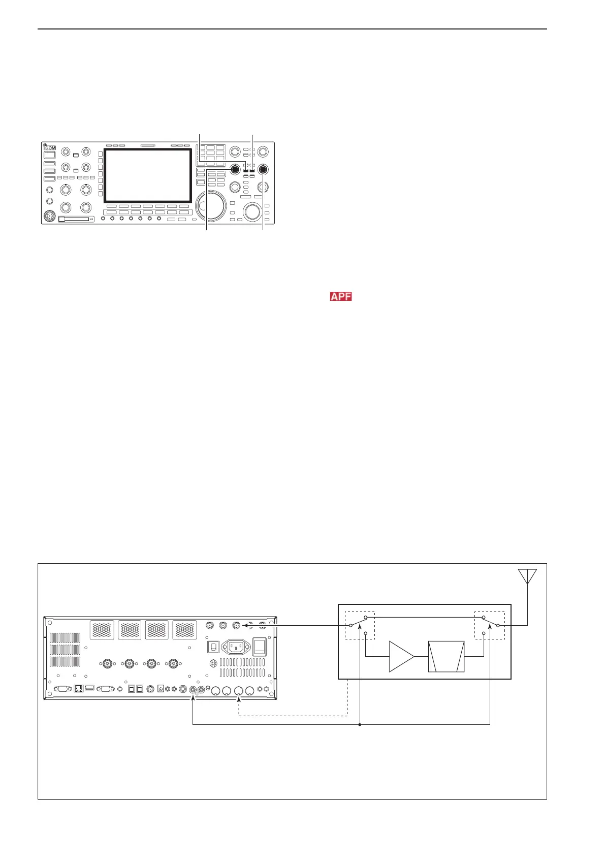
D About 137 kHz band operation (Europe, UK, Italy, Spain, France versions only)
137 kHz band, within the 135.7 kHz to 137.8 kHz
range, operation in CW mode is optionally available
with the IC-7800.
TheRFsignalfrom[X-VERTER]isusedforthe137
kHz band operation, and an external amplifier unit is
necessary.
See the connection diagram below for reference.
• Connection diagram for 137 kHz band operation
PA
BPF
or
LPF
Power amplifier with T/R switching unit
for 137 kHz
to [X-VERTER]
to [RELAY] (for transmit/receive control)
to [ACC2] pin 6*
*Transverter ON/OFF control signal related to the power amplifier
unit main power, if desired.
• ON: 2–13.8 V DC input (more than 10 kΩ impedance)
• OFF: Less than 2 V DC
Set the transverter offset in the Others
set mode as “0.000 MHz.”
See page 12-16 for details.
NOTE:
4
RECEIVE AND TRANSMIT
 Loading...