13-2
■ Remote interface (CI-V) information
DD
CI-V connection example
The receiver can be connected through an optional
CT-17 CI-V LEVEL CONVERTER to a PC equipped with an
RS-232C port. The Icom Communications Interface-V
(CI-V) controls the receiver.
Up to 4 Icom CI-V transceivers or receivers can be
connected to a PC equipped with an RS-232C port.
See p. 11-14 for configuring the CI-V using set mode.
DD
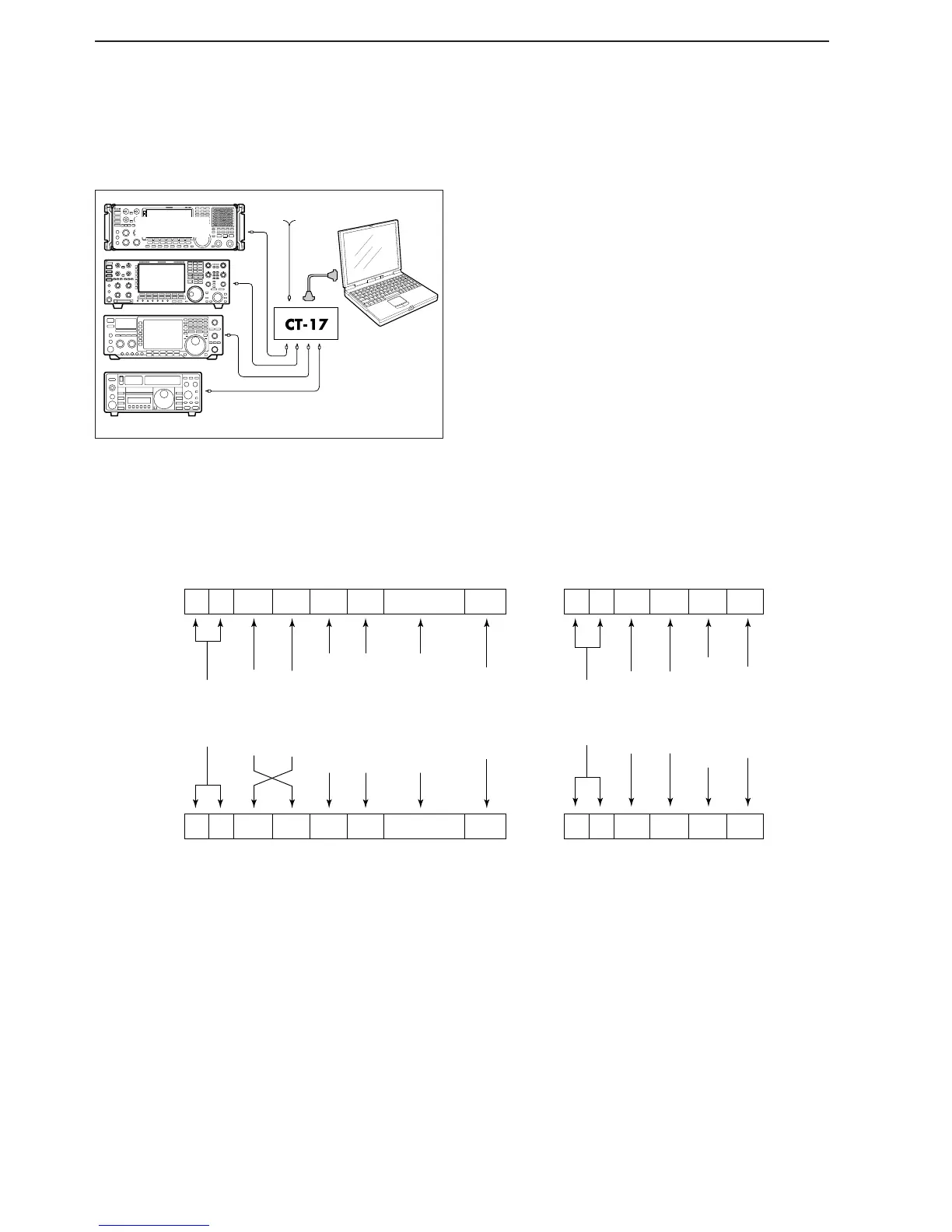
Data format
The CI-V system uses the following data formats.
Data formats differ according to command numbers. A
data area or sub command is added for some com-
mands.
 Loading...