3 Peripheral Devices and Options
-
100
-
Controller Model
Power of
Applicable
Motor (kW)
Max.
Resistance
of Regen.
Min.
Resistance
of Regen.
Power
(W)
Braking Unit
NICE-L-C-4075
75 16×2 13×2 12000×2
MDBUN-
60-T×2
NICE-L-C-4075F
NICE-L-C-4090 90 14×2 13×2 13500×2
MDBUN-
60-T×2
NICE-L-C-4110 110 12×2 9×2 18000×2
MDBUN-
90-T×2
NICE-L-C-4132 132 13.5×3 10.5×3 14000×3
MDBUN-
90-T×3
NICE-L-C-4160 160 12×3 9×3 18000×3
MDBUN-
90-T×3
◆
This algorithm takes the synchronous motor as an example. The
reduce the power of the regen. resistor or increase the resistance of the
regen. resistor.
◆
It is recommended to select a resistance as close to the min. resistance as
possible during the selection of a resistor.
◆
×2 indicates two sets of corresponding accessories are required. For
must be connected in parallel to the controller.
◆
×3 indicates that 3 groups must be connected in parallel.
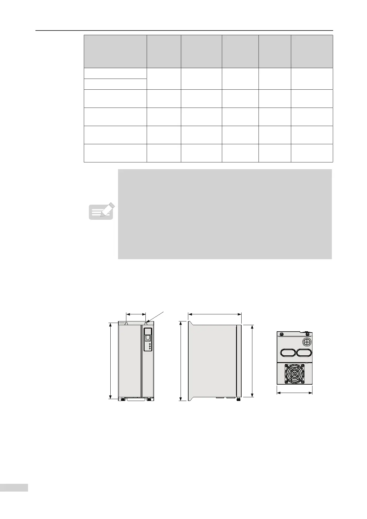
2 Braking Unit
■
Physical dimension diagram of MDBUN series braking unit
Appearance and mounting dimension diagram of braking unit (unit: mm)
 Loading...