3 Peripheral Devices and Options
-
123
-
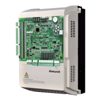
3.3.5 Group Control Board (MCTC-GCB-A)
A single group control board (GCB) (standard program) supports group control of 4
Combination of two GCBs (customized program) supports group control of 5 to 8 ele-
us.
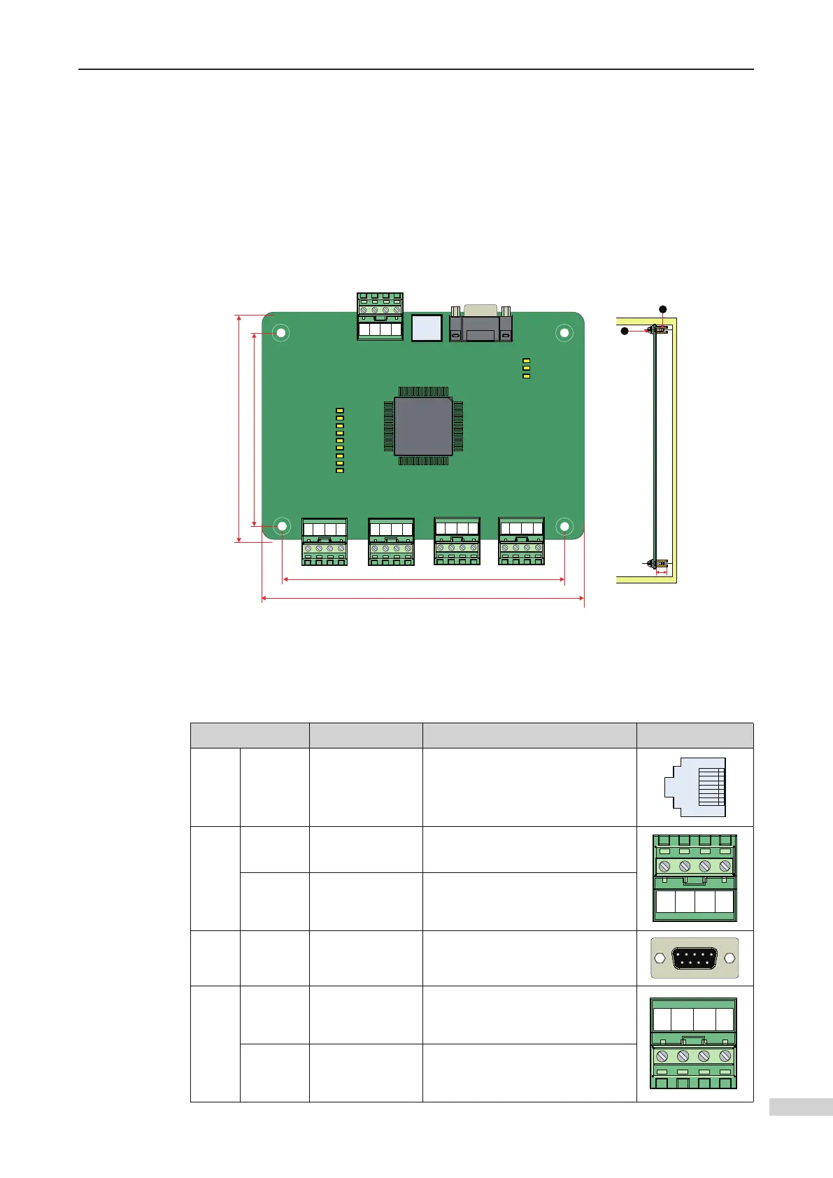
1 Appearance and dimensions
24V
CAN1+
CAN1-
COM
24V
CAN2+
CAN2-
COM
24V
CAN3+
CAN3-
COM
24
V
CAN4+
CAN4
-
COM
D37
D40
D41
D42
D43
D44
D45
D46
D47
D5
D3
D2
125
115
152
162
CN2
CN1 CN3
CN7
CN9 CN8 CN10
COM
485+
485-
+24V
2
1
1 - Plastic support higher than 1 cm
2 - Combination screw M4x10
8.8
MCTC-GCB
Appearance, dimensions, and installation method of the MCTC-GCB-A
2 Description of terminals
Input and output terminals of the MCTC-GCB
Terminal ID Terminal Name Function description Terminal Layout
CN1 -
Operation panel
terminal
Connecting the operation panel
CN2
+24V/
COM
24 VDC power
supply
External 24 VDC power supply for
the entire GCB
MOD+/
MOD-
Modbus
communication
terminal
LCD display and extension
functions
CN3 - RS232 Interface
Communicating with the host
computer or IE card
CN7
+24V/
COM
External 24 VDC
power supply
24 VDC power supply for
the corresponding CANbus
communication module
CAN1+/
CAN1-
CANbus
communication
terminal
CANbus communication between
the GCB and the MCB of elevator 1
in group control
 Loading...