5 System Commissioning
-
145
-
5.3 Power-on and Controller State Check
5.3.1 Checking Power-on State
□√
No. Check Contents
1
Apply the power. Check that the line voltage of the R, S, T phases of the
of R, S, T cables on the controller.
2
Check that the power input voltage of the 24 V terminal (CN3) on the MCB
power supply and check whether the 24 VDC circuit is wired correctly.
5.3.2 State Check at Normal Power-on
□√
No. Check Contents
1
Check that the keypad has display after power-on. If there is no display on
the keypad, check whether the power supply of the controller is normal.
2
indicates that the 24 VDC power supply is normal, and the X input terminals
work properly. If none of the indicators is ON, it indicates that the 24 VDC
power supply is abnormal, and you need to eliminate the problem.
CN1
CN
9
CN12
J12
PRG
UP
SET
J9
J10
CN2
CN7
CN3 CN4
J6
J5
J7
J1
NICE3000
new
integrated elevator
controller
X1
X2
X3
X17
X18
X19
X20
X21
X22
X23
X24
J13
J14
J8
X4
X5
X6
X7
X8
X9
X10
X11
X12
X13
X14
X15
X16
COP
HOP
CAN2
MOD2
232
X25
X26
X27
X28
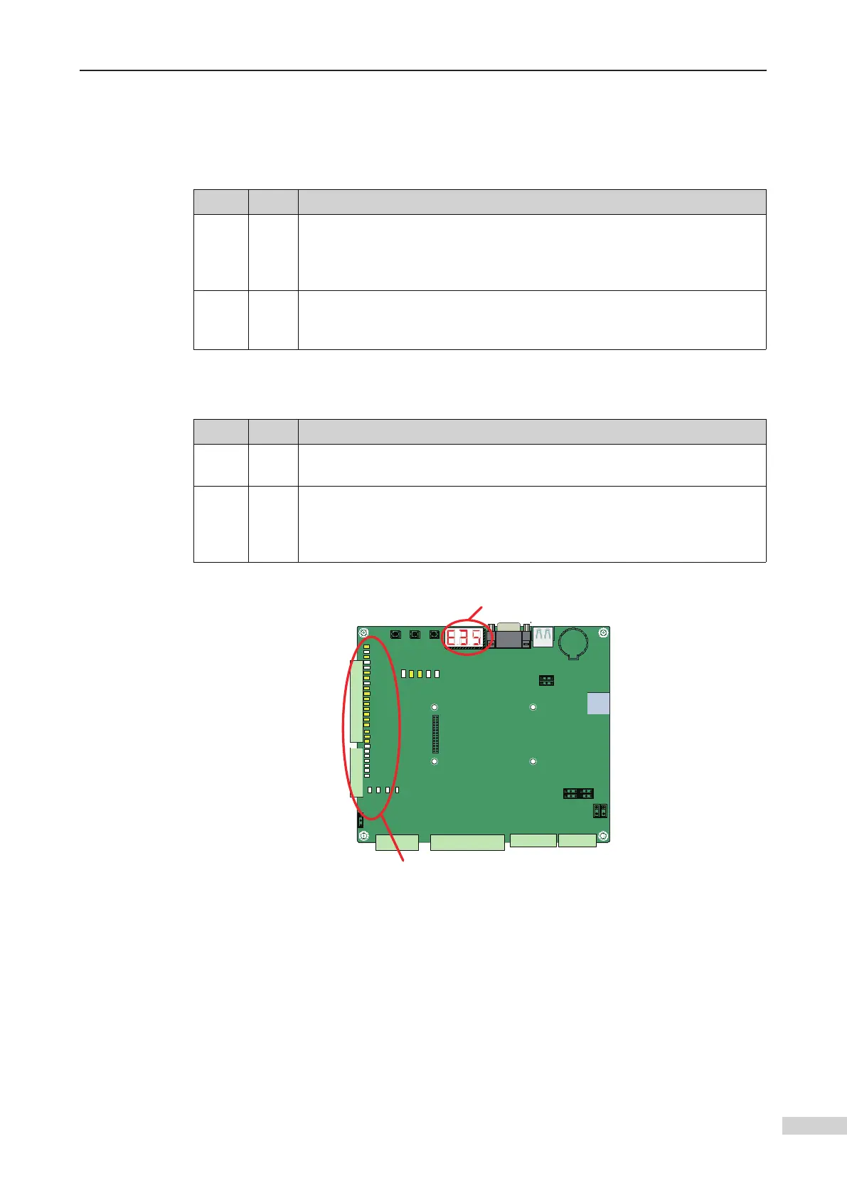
a. There is display on the
LEDs.
b. Certain inputs on the MCB are active.
MCB display after normal power-on
5.3.3 Potential Controller States and Handling Methods Before Commissioning
1 Check the controller state and handle related faults accordingly as follows:
-
cause the conditions for automatic elevator running are not met and certain peripher-
al signals are not connected. Such faults include E41, E42, E35, E51, E52, and E58. The
following part describes the MCB state at fault and handling of these faults.
 Loading...