2 Installation and Wiring
-
64
-
-
+
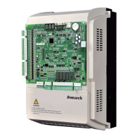
A
D
ARM
Differential
input
M
Ai
Operational
amplifier
CN9
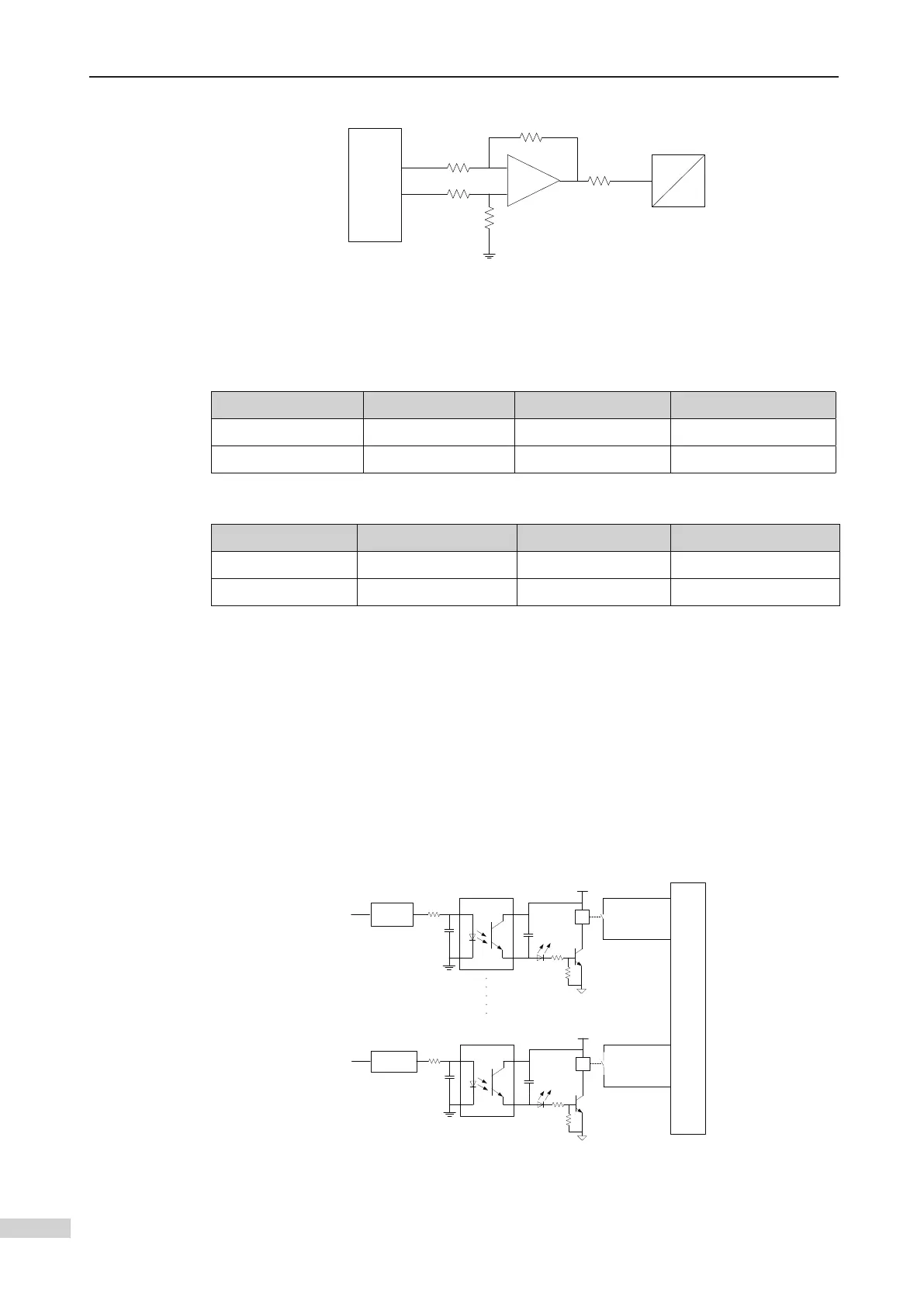
2.3.3 Relay Output (DO)
Relay Quantity Code Function Code
Y1/Y2/Y3 3 Y1/M1 to Y3/M3 F5-26 to F5-28
Y4/Y5/Y6 3 Y4/M4 to Y6/M6 F5-29 to F5-31
Relay characteristics
Relay Rated load Maximum current Response time
Y1/Y2/Y3 5 A 250 VAC/30 VDC 10A 10 ms
Y4/Y5/Y6 5 A 250 VAC/30 VDC 5A 10 ms
A total of six relay outputs are provided. The optocoupler isolated ARM I/O signals
control the relay line package current. After the line package is energized, the
corresponding signal indicator becomes ON. The relay outputs do not have the
common ground.
The inductive load (relay, contactor, and motor) causes voltage peak after the current
is removed. A TVS is used for protection at the Y1/M1 to Y3/M3 contacts of the relay,
Y3/M3 correspondingly. In addition, XCOM on the high voltage detection terminal CN4
must be connected to the 110 V neutral line of the safety circuit. No absorption circuit
VCC
I/O
ARM
Optocoupler
DO
Y1
M1
Relay
VCC
I/O
Optocoupler
Y6
M6
Relay
CN7
BUFFER
BUFFER
Relay output circuit
 Loading...