2 Installation and Wiring
-
78
-
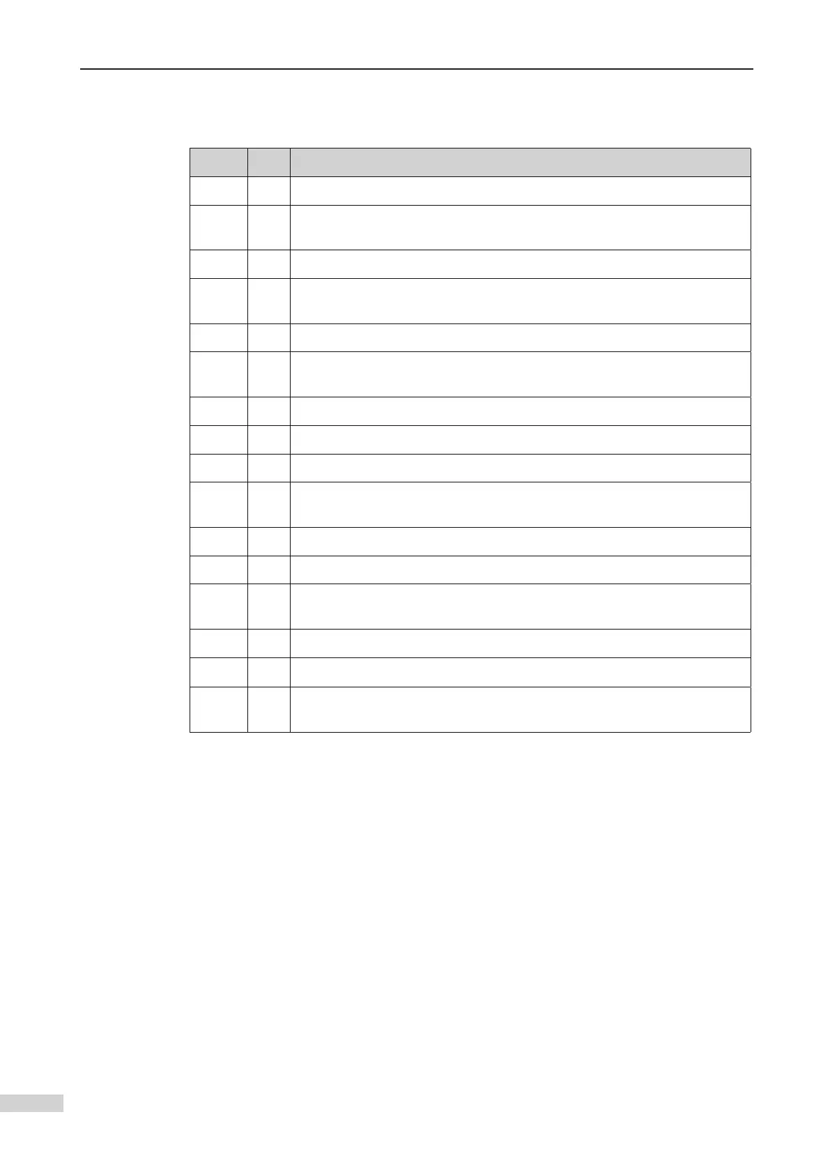
2.5.2 Wiring Inspection
Wiring checklist
□√
No. Contents
1 Check the controller model to ensure receipt of correct model.
2
breaker) meet the design requirements.
3 Check the optional board models to ensure receipt of correct model.
4
The installation method and environment of the controller meet the
requirements.
5
6
The rated motor voltage is consistent with the output ratings of the
controller.
7 Wire the power input cables to R, S, T terminals of the controller correctly.
8 Wire motor cables to U, V, W terminals of the controller correctly.
9 The cable size of the main circuit meets the requirements.
10
Check whether the motor cables exceed 50 m. If yes, decrease the carrier
frequency set in F0-07.
11 Check whether the grounding cable is grounded properly.
12 The output terminals and control circuit terminals are wired securely.
13
Check correct wiring of the braking components and proper resistance of
the regen. resistor.
14 The control circuit signal cables use the shielded twisted pair.
15 The optional boards are wired correctly.
16
The control circuit cables are separated from the main circuit cables during
cabling.
2.5.3 Parameter setting
Figure 2-37 shows the wiring of the NICE3000
new
system. The functions of I/O terminals
of the controller are set using parameters in group F5. The connection method shown
 Loading...