3 Peripheral Devices and Options
-
119
-
■
Description of terminals
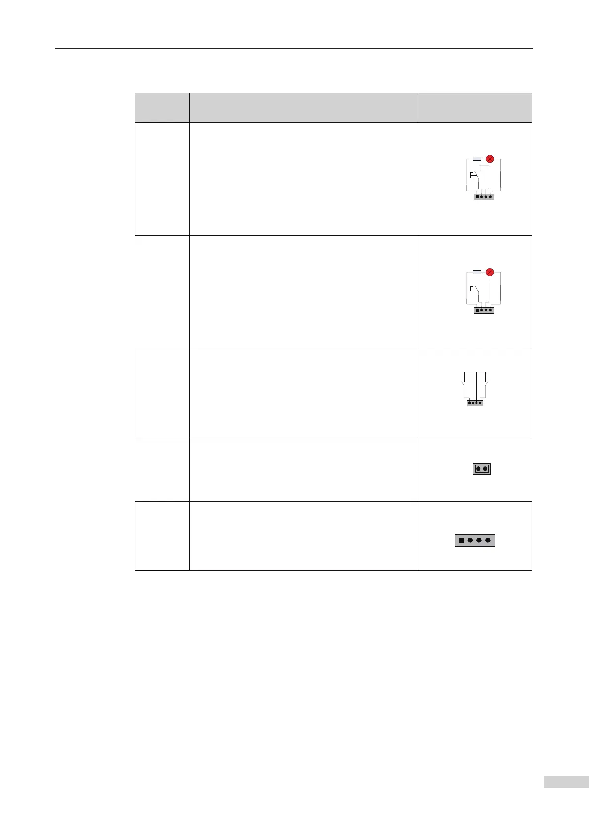
Input and output terminals of HCB-H
Terminal
Name
Function
Connection between
MCTC-PG and encoder
UP
Interface for the up call button
Pins 2 and 3 are for up call input. Pins 1 and 4 are
power supply for the up call indicator
(24 VDC output, load capacity: 40 mA).
1 2 3 4
Up call indicator
Up call
button
DOWN
Interface for the down call button
Pins 2 and 3 are for down call input. Pins 1 and 4 are
power supply for the down call indicator
(24 VDC output, load capacity: 40 mA).
1 2 3 4
Down call indicator
Down call
button
XF/ST
switches
Pins 1 and 2 are for elevator lock input. Pins 3 and 4
1 2 3 4
Fire
emergency
input
Elevator
lock input
J1
Short J1, and press the UP button or DOWN button
jumper cap is removed, the address is automatically
stored.
CN1
Modbus communication and power supply terminal
Pins 2 and 3 are for Modbus communication. Pins 1
and 4 are for power supply.
 Loading...