3 Peripheral Devices and Options
-
126
-
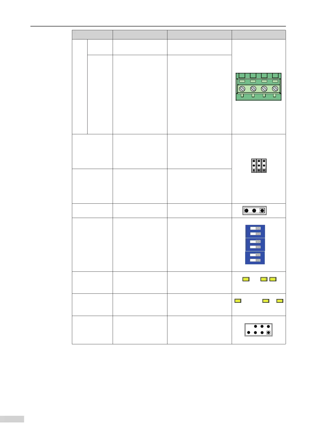
Terminal ID Terminal Name Function description Terminal Layout
J5
+24V/
COM
24 VDC power supply External 24 V power supply
MOD+/
MOD-
RS485 communication
interface with the MCB
This interface is reserved
when the expansion board
is placed at the top of the
car.
When the extension
board is installed in the
equipment room, one
signal can be used for
calls of the back door,
implementing opposite
door control of all 40
J6/J7
MOD termination
resistor jumper pin
When Modbus
communication is used,
J6/J7 is shorted to the ON
pin to connect a matching
resistor.
J10
CAN termination
resistor jumper pin
When CANbus
communication is used,
J10 is shorted to the ON
pin to connect a matching
resistor.
J3 Reserved Factory reserved
J3
S1/S2/S3 Address DIP switch
These switches are used to
set an expansion type.
When all switches are OFF,
this board is on top of the
car.
When K1 is in ON position,
this board is in the
equipment room.
X1 to X10 DI indicator
This indicator is on (green)
when the external input is
active.
Y1 to Y10 Relay output indicator
This indicator is on (green)
when the system output is
active.
J9 Reserved
Factory reserved. Do
not short it randomly.
Otherwise, the controller
may not work properly.
 Loading...