3 Peripheral Devices and Options
-
128
-
2 Description of terminals
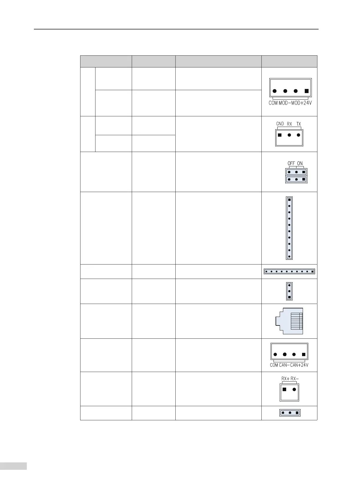
Description of MCTC-MIB-A terminals
Terminal ID Terminal Name Function description Terminal Layout
J12
+24V/COM
External 24 VDC
power supply
External 24 V power supply
MOD+/MOD-
RS485
communication
interface
Connecting the MIB in the
monitoring room for RS485
communication
J11
TX/RX
RS232
communication
Burning program disconnection/
Communication interface
with the PC host computer/
Communication interface with
the controller
GND GND interface
J14/J15
Matching
resistor
The board terminal in the
monitoring room is connected to
part 1. The board terminal in the
equipment room is connected to
part 2 (by default).
J4/J7 GSM module
Connecting the short message
GSM module
J5/J8 Zigbee module Reserved
J1 Burning jumper
ON: The jumper is active and
enters the download mode.
J10
Operation panel
interface
Connecting the operation panel
J3 Reserved -
J13 Reserved -
J6 Reserved -
 Loading...