9 Description of Functions and Schemes
-
305
-
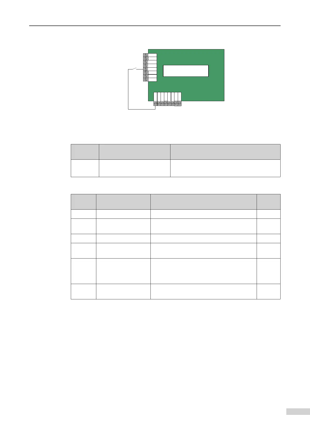
Scheme 2. Elevator lock input from MCB
MCTC-MCB-C2
CN4
M24
CAN2+
CAN2-
MCM
MOD2+
MOD2-
X17
X18
X19
X20
X21
X22
X23
X24
CN2
Elevator
lock
signal
AL+
AL-
CN6
Wiring diagram of elevator lock signal input from MCB
Function
Code
Name Setting Range
F5-21 X21 function selection
28: Elevator lock signal NO
60: Elevator lock signal NC
3 Parameters
Function
Code
Name Setting Range Default
F6-04 F6-01 to F6-00 1
F6-38
Elevator lock start
time
00.00 to 23.59 0
F6-39 Elevator lock end time 00.00 to 23.59 0
F6-40
Program control
selection 1
Bit5: Timed elevator lock 0
F6-41
Program control
selection 2
Bit8: Elevator lock at door open
Bit9: Display available at elevator lock
Bit10: Elevator lock in the attendant state
0
F6-42
Program control
selection 3
Bit5: Clearing calls immediately at elevator
lock
0
The input setting of the elevator lock function is as follows:
Generally, the elevator lock signal is input via the elevator lock switch on the HCB of
input terminal Xd as an example) according to the preceding table.
 Loading...