D-0120588-B – 2019/03
Eclipse – Instructions for Use - EN Page 60
4.1 Preamplifier setup
When the VEMP test type is selected, the preamplifier will automatically set the gain lower (from 80dB to
60dB), in order to handle the large muscle potentials of the response.
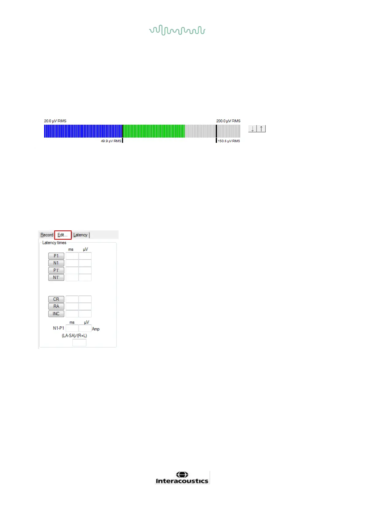
4.2 VEMP monitor
The VEMP monitor displays the ongoing EMG contraction/activity during testing. The two black vertical bars
on the display indicate the desired contraction range for testing. When the patient’s EMG contraction falls
within the defined range the bar will turn green, the stimulus is presented to the patient’s ear and responses
are recorded. When the EMG contraction falls above or below the defined range, the bar will appear in red
(for right ear) and blue (for left ear). Adjust the defined EMG contraction range, by dragging the black bars to
the desired limit with the mouse.
The VEMP monitor is disabled when running the oVEMP factory protocols.
4.3 VEMP waveform markers
P1 and N1 markers are available for marking the positive peaks and
negative troughs of the waveform. In addition, P1’ and N1’ markers are
available when multiple tracings of the same intensity have been run.
Absolute latency and amplitude data are displayed in the corresponding
ms and µV fields after waveforms have been marked.
 Loading...