System-Related Functions
Copyright ©ITECH Electronic Co., Ltd. 74
Digital IO-7
IO-7 can be set to【Trigger2-in】, 【Trigger2-out】, 【Input】,【Output】
【Trigger2-in】: The input trigger signal, the pulse signal sent to the IO-6 pin can
be used as the trigger source. Users can select as the trigger source of the
corresponding function in the menu.
【Trigger2-out】: The output trigger signal, when the instrument generates a
trigger signal, the pin7 generates an pulse signal.
5.14 Analogue Function (Ext-Program) (Optional)
The interface expansion slot provided on the rear panel of the IT7800 series.
This function is not standard with the instrument and is optional for users.
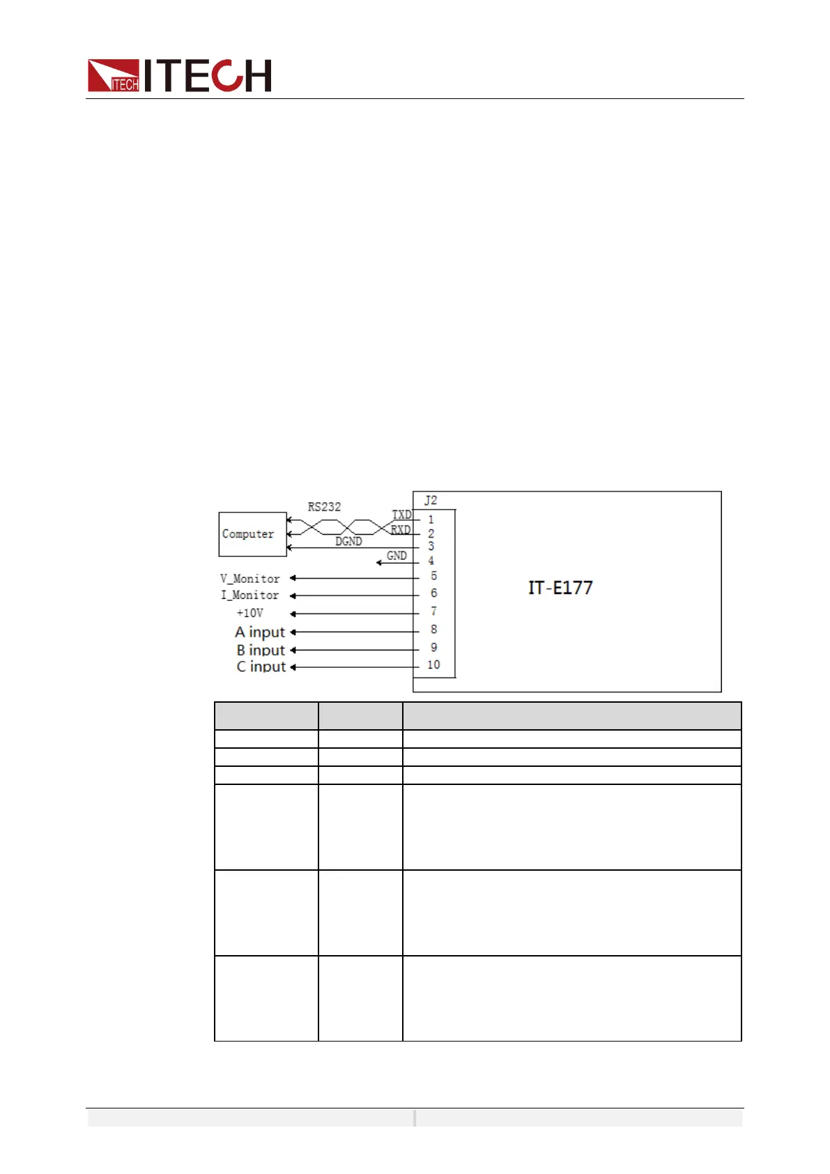
When the interface card selected by the user is RS232+Analog interface (IT-
E177), the analog interface can realize the external analog function.
⚫ Remotely control voltage
⚫ Power amplifier function
⚫ Remotely monitor voltage and current values
The pins description is as below.
Grounding of analog signals,
Set the voltage of A phase.
When output is DC, –10V ~ 10V voltage value to
set the voltage between negative full range and
positive full scale. When output is AC, 0-10V
voltage value to set the 0 to full scale.
Set the voltage of B phase.
When output is DC, –10V ~ 10V voltage value to
set the voltage between negative full range and
positive full scale. When output is AC, 0-10V
voltage value to set the 0 to full scale.
Set the voltage of C phase.
When output is DC, –10V ~ 10V voltage value to
set the voltage between negative full range and
positive full scale. When output is AC, 0-10V
voltage value to set the 0 to full scale.
Enable/disable analog control
The user needs to select the corresponding function settings in the System
 Loading...