EasyManua.ls Logo

ITech IT7800 Series User Manual

ITech IT7800 Series
118 pages
To Next Page IconTo Next Page
To Previous Page IconTo Previous Page
Page #98 background image
Technical Specifications
Copyright ©ITECH Electronic Co., Ltd. 96
Communication
interface
Built-in USB/CAN/LAN/Digital IO interface, optional GPIB /
Analog&RS232
*1 supports single phase 220V input, power cord connecting refer to manual.
*2 According to the output frequency, the output voltage will be reduced, the rated voltage can be out within 1.4K, the
maximumoutput voltage at 2KHz is 253VRMS and 2.4KHz is 211VRMS.
*3 When loopSpeed Low is low
it can better complied DUT’s characteristics
When LoopSpeed is High
the dynamic response
time is faster.
*4 The dynamic response time test condition is: DC high-speed mode, and the capacitance of the DUT to be less than 10uF
All the above parameters are subject to change without prior notice from ITECH
IT7805-350-30U
Input parameters
AC input
Wiring connection
3 phase 3wire + ground(PE) *1
Line voltage
RMS
( 200
220
) ±10%*2
( 380
480
) ±10%
V
Line current
RMS
< 20
A
Apparent power
< 5.8
kVA
Frequency
45
65
Hz
Power factor
typ
0.98
Output parameters
AC Output
Output voltage
VLN *3
0
350
V
Output current
RMS1phase
30
A
Crest
Factor
3
Peak1phase
90
A
Output power
Max.
Power
1phase
5k
VA
Voltage setting
Range
1phase
0
350
V
Resolution
0.01
V
Accuracy
16Hz
500Hz
0.1%+0.1% F.S
500.01Hz2.4kHz
0.1%+(0.2%*kHz)F.S
Temperature
coefficient
< 100ppm/
F.S
DC Voltage offset
typ
0.02
Vdc
Current Limit setting
Range
RMS
1phase
30
A
Resolution
0.01
A
Accuracy
DC,16Hz150Hz
0.1% + 0.2% F.S.
150.01Hz500Hz
0.2% + 0.3% F.S.
500.01Hz2.4kHz
0.3%+(0.6%*kHz)
F.S
Temperature
coefficient
< 200ppm/
F.S
Frequency
Range
Low *4
16
500
Hz
High *4
16
2.4k
Hz
Resolution
0.01
Hz
Accuracy
16Hz
500Hz
0.01%
500.01Hz
2.4kHz
0.1%
waveform synthesis
50/60Hz
up to 50
order
s
Phase
Range
0
360
°
Resolution
0.1
°
DC Output
Voltage setting
Range
1phase
-495
495
Vdc
Resolution
0.01
V
Accuracy
0.1%+0.1% F.S
Temperature
coefficient
< 100ppm/
F.S
Current setting
Range
1phase
-30
30
Adc
Resolution
0.01
A
Accuracy
0.3%+0.3% F.S
Temperature
coefficient
< 200ppm/
F.S
Max. power

Table of Contents

Question and Answer IconNeed help?

Do you have a question about the ITech IT7800 Series and is the answer not in the manual?

ITech IT7800 Series Specifications

General IconGeneral
BrandITech
ModelIT7800 Series
CategoryAC Power Distribution
LanguageEnglish

Summary

Safety Symbols

Safety Precautions

Environmental Conditions

Regulatory Markings

Compliance Information

EMC Standard

Electromagnetic Compatibility standards the instrument complies with.

Safety Standard

Safety standards the instrument adheres to.

Chapter 1 Quick Reference

1.1 Brief Introduction

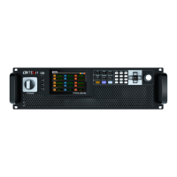
Overview of IT7800 series features and applications.

1.2 Front Panel Introduction

Description of the IT7800 front panel components and layout.

1.3 Keyboard Introduction

Explanation of the IT7800 series keyboard layout and key functions.

1.4 Push-on Knob

Details on the function and operation of the push-on knob.

1.5 Rear Panel Introduction

Explanation of the IT7800 series rear panel connectors and ports.

1.6 Home-Screen Overview

Overview of the IT7800 series home screen interface and navigation.

1.7 Optional accessories

Information on optional accessories available for the IT7800 series.

Chapter 2 Inspection and Installation

2.1 Unpacking and Transportation

Instructions for safely unpacking and transporting the instrument.

2.2 Verifying the Shipment

Steps to verify shipment contents and check for damage.

2.3 Instrument Size Introduction

Dimensions and physical specifications of the IT7800 series instruments.

2.4 Connecting the Power Cord

Procedures for connecting the power cord and AC input.

2.5 Connecting Test Lines (Optional)

Guidance on connecting test lines and the DUT.

2.6 Installing Fiber Cables (Only for IT7830-350-180)

Instructions for installing fiber optic cables for specific models.

Chapter 3 Getting Started

3.1 Power-on the Instrument

Steps and precautions for powering on the instrument.

3.2 Touch Screen Introduction

Explanation of the touch screen interface and navigation.

3.3 Set output parameters

How to set voltage and frequency output parameters.

3.4 Output On/Off Control

Instructions for controlling the output power on and off.

Chapter 4 Operation and Application

4.1 Select the Power Supply Mode

How to select single-phase, three-phase, reverse, or multi-channel modes.

4.2 Select the Output Mode

How to select AC, DC, AC+DC, or DC+AC output modes.

4.3 Waveform Selection

How to select and configure output waveforms.

4.4 Auto-range Function

Explanation of the auto-ranging feature for voltage and current.

4.5 Output Characteristic

Understanding the output voltage and current characteristics.

4.6 Current Limit Mode and Power Limit Mode

How to set and use current and power limit modes.

4.7 Sweep Function

Using the sweep function to test efficiency and parameters.

4.8 Power Amplifier

Using the instrument as a power amplifier.

4.9 Programmable Output Impedance

Simulating AC grid impedance.

4.10 Polyphase Function

Configuring multi-phase output using system bus or digital IO.

4.11 Standard IEC Regulations

Using standard IEC regulation test curves and customization.

Chapter 5 System-Related Functions

5.1 System Menu Reference

Overview of the system menu and its options.

5.2 Configuration Menu Reference

Detailed configuration settings for DC, AC+DC, and AC modes.

5.3 Key Lock Function

How to lock and unlock the instrument's keyboard.

5.4 Switching Local/Remote Mode

How to switch between local and remote control modes.

5.5 Save and Recall Operations

Procedures for saving and recalling instrument settings.

5.6 Protection Function

Setting up overcurrent, voltage, and temperature protection functions.

5.7 Screen Capture Function

Capturing and saving screen images to a USB disk.

5.8 Trigger Function

Configuring trigger sources and modes for events.

5.9 Query the System Log

Accessing and viewing system operation logs.

5.10 Query the Energy

Using the energy statistics function.

5.11 Set Parallel Operation Mode

Configuring multiple instruments for parallel operation.

5.12 Remote Measurement Function

Setting up and using remote measurement and sensing.

5.13 Digital I/O Function

Configuring digital I/O pins for control and signaling.

5.14 Analogue Function (Ext-Program) (Optional)

Using optional analog interfaces for control and monitoring.

Chapter 6 Measurement Functions

6.1 Meter Mode

Using the instrument as a basic meter for electrical measurements.

6.2 Oscilloscope Mode

Displaying and analyzing voltage and current waveforms.

6.3 Harmonic measurement

Measuring and analyzing harmonic parameters.

6.4 Recorder Function

Recording and observing output status data over time.

Chapter 7 Configuration Arbitrary Waveform

7.1 List Function

Creating and executing sequences of AC waveforms using List files.

7.2 Setting of Surge/Sag Configuration

Simulating surge and sag for abnormal voltage fluctuations.

7.3 Self-defined Waveform Function

Customizing and saving user-defined output waveforms.

7.4 Voltage Signals Simulation

Importing and simulating voltage signals using waveform files.

Chapter 8 Technical Specifications

8.1 Main technical parameters

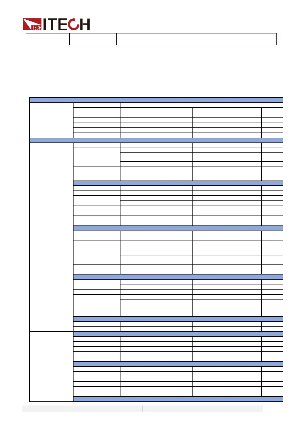
Detailed technical specifications for IT7800 series models.

8.2 Supplemental characteristics

Additional characteristics like calibration and cooling.

Chapter 9 Remote Control

9.1 USB Interface

Connecting and configuring the instrument via USB.

9.2 LAN Interface

Connecting and configuring the instrument via LAN interface.

9.3 CAN Interface

Configuring and using the CAN communication interface.

9.4 GPIB Interface (Optional)

Setting up and using the optional GPIB interface.

9.5 RS-232 Interface (Optional)

Setting up and using the optional RS-232 interface.

9.6 Commonly Used Commands Overview

Overview of common SCPI commands for remote operation.

9.7 Demo Software Introduction

Information on control software for remote operation.

Related product manuals