System-Related Functions
Copyright ©ITECH Electronic Co., Ltd. 76
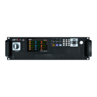
Power Amplification
Analog signals can be input through the analog input interface and power
amplification function can be realized. The operation method is as follows:
Connecting the analog interface, different interface function are different, please
refer to pins description as above.
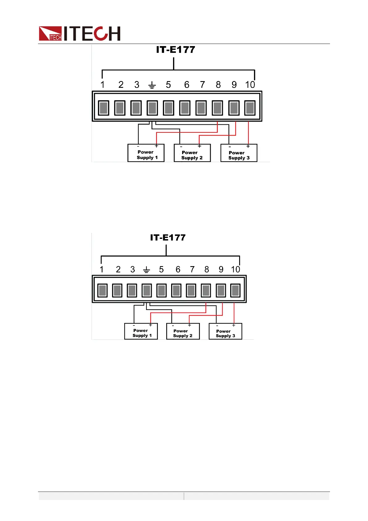
Voltage and current monitoring
Through the analog interface, the existing output voltage/current can be
monitored. Connect a digital voltmeter or oscilloscope between pin 54
(V_Monitor), pin 6 (I_Monitor) and ground wire 4 (GND) of the analog interface.
The -10V ~ 10V voltage reading corresponds to the power voltage and current
output between negative full range and positive full scale (For AC, 0 to 10V
corresponds to 0 to full scale).
For example, Monitoring AC range of 0~350V voltage, when themonitoring
voltage is 5V, the voltage ratio set to 50V/1 under source menu, the input voltage
is 5*50=250V. The wiring diagram is shown in the figure below.
 Loading...