- Restore the electrical connections.
Tightening torque should be as follow:
Terminal 30: 20 ÷ 30 Nm
Terminal G: 20 ÷ 30 Nm
Terminal 50: 2 ÷ 3Nm
Apply a light layer of Vaseline onto the terminals
to protect them from rusting.
- Check the engine starting.
Figure 35
The starter motor is located on the left-hand side of the
flywheel housing in an area fairly easy to access from the
bottom. Its disassembly requires no special tools an d is not
particularly difficu lt. Proceed as follows:
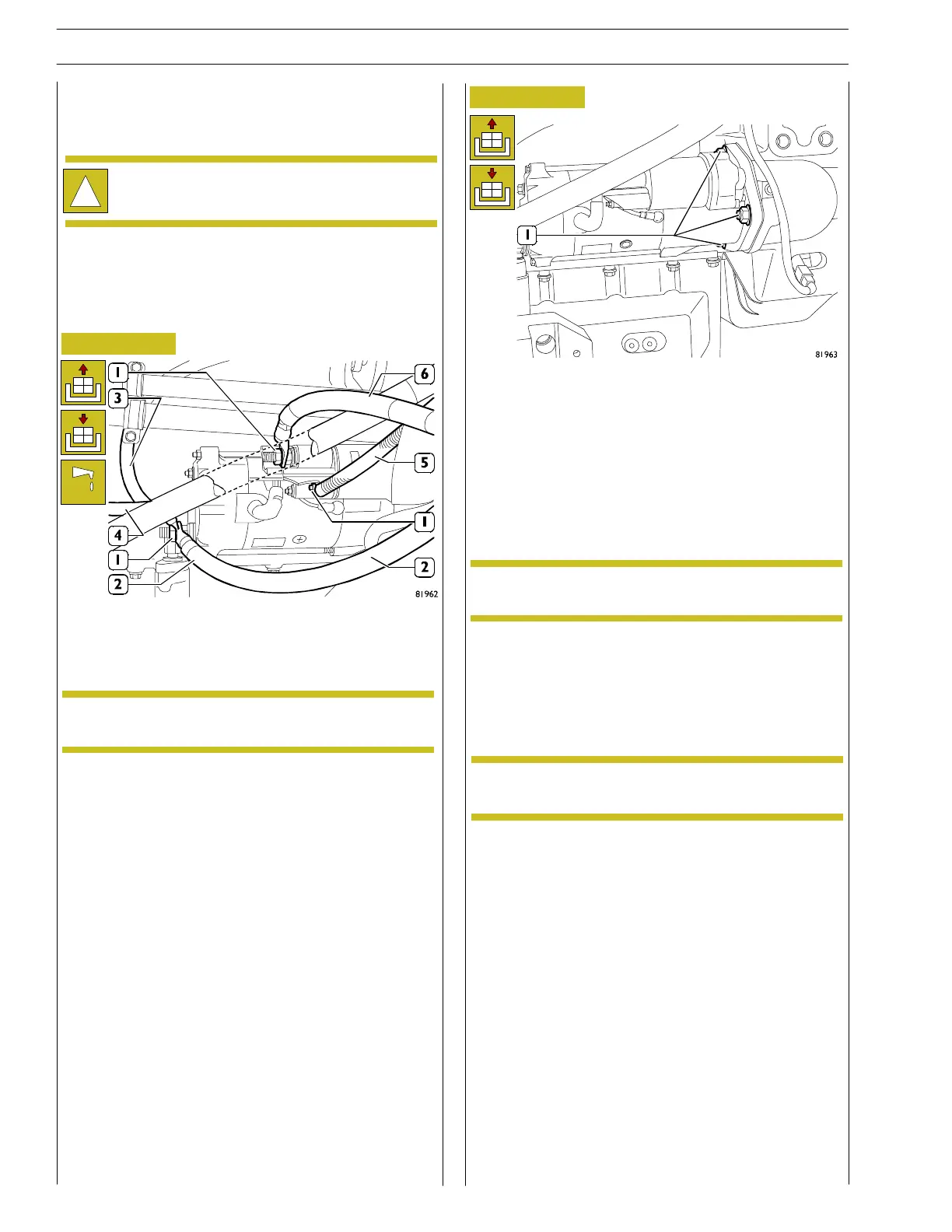
- Unscrew the nuts (1). Disconnect the electrical
con nections of cables (2), (3), (4), (5) a nd (6).
- Remove the starter motor by unscrewing the nuts (1).
Fitting
- Change the motor with a new one and position it in its
seat after chang ing the gasket between the flywheel
housing and the motor. Tighten the fixing nut (M12 x
1.75) to a torque of 105 ÷ 86 Nm.
!
Before proceeding to work on an electric or
electronic component, make sure the system is not
powered.
It is recommended to mark t he cables in order to
make a secure connection in the assembly phase.
Figure 36
REMOVING/REFITTING STARTER MOTOR
Removal
NOTE
NOTE
NOTE
Always change the gasket w it h a new one. Do not
reuse the one removed.
98
SECTION 3 - INDUSTRIAL APPLICATION
VECTOR 8 ENGINES
Base - April 2006 Print P2D32V001E
 Loading...
