Figure 79
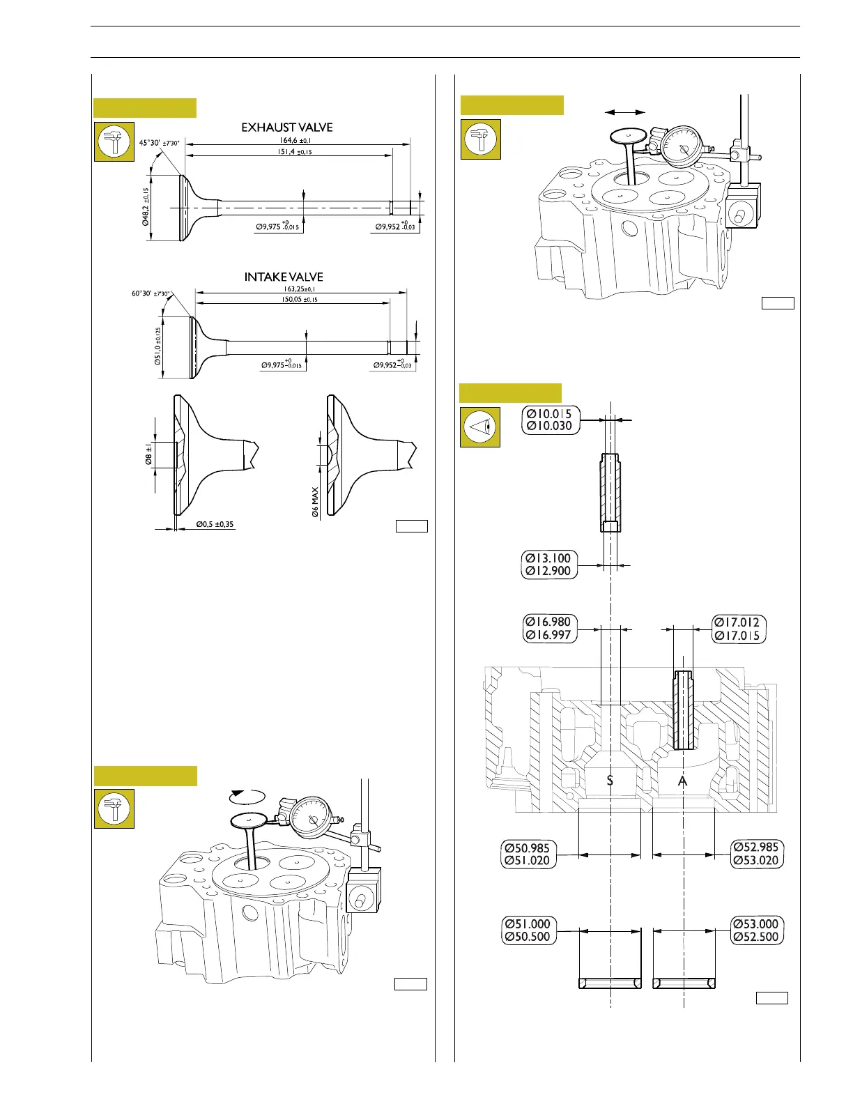
VALVE GUIDES
These checks are carried out using a magnetic support dial
gauge which is positoned as shown in the figure above.
By rotating the valve check that the centering error does not
exceed 0.03 mm.
Figure 80
Checking valve centering
Figure 81
These checks are carried out using a magnetic support dial
gauge which is positoned as shown in the figure above.
The mounting clearance is from 0.045 to 0.070.
Checking clearance between valve stem
Figure 82
Refacing the valves
MAIN DATA OF THE VALVE SEATS AND VALVE GUIDE
SEATS ON THE CYLINDER HEADS
A=INLET—S=EXHAUST
A. Intake valve on the engines with serial numbers starting up
to 484 - B. Intake valve on the engines with serial numbers
starting from 485
- Check with a micrometer that the diameter of the valve
stems is as indicated; if necessary, rebore the seats on the
valves with the grinding machine, removing as little material
as possible.
After machining, check that the dimensions c ome within
thepermissibletolerance.
A
B
103185
89832
83492
89766
SECTION 4 - OVERHAUL AND TECHNICAL SPECIFICATIONS 35
VECTOR 8 ENGINES
Print P2D32V001E Base - April 2006
 Loading...
