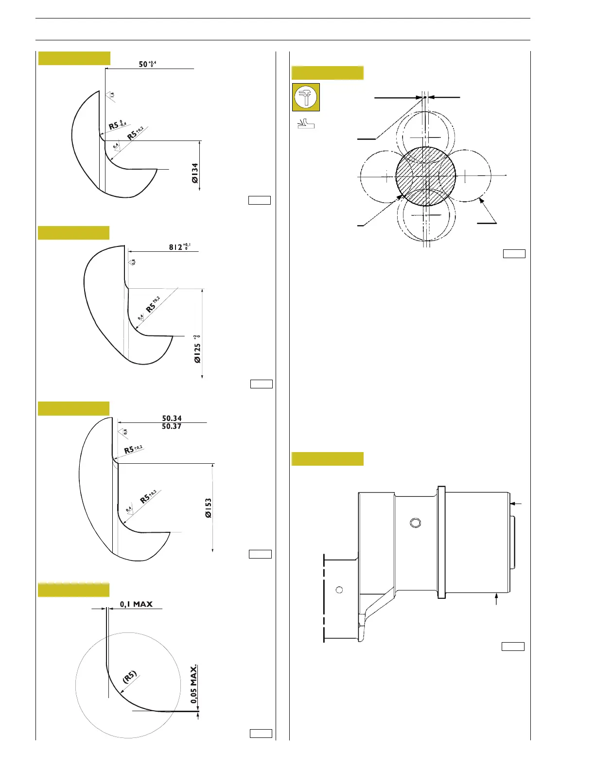
The tolerances allowed on the engine shaft pins are:
- ovality = 0.007 mm
- taper 0.012 mm
- main journal misalignment 0.10 mm
- crankpin misalignment ± 0.025 mm
- tolerance on the distances between the axis of the
crankshaft and the outside of each crankpin ± 0.10 mm
Figure 23
Figure 24
Figure 25
Detail of couplings of central main journal.
Detail of couplings of crankpin.
Detail of couplings of rear — thrust main journal.
Checking main journal alignment
LIMIT POSITION
LIMIT POSITION
NORMAL POSITION
MAIN JOURNAL
CRANKPIN
Diagram for checking the flywheel mating surface is orthogonal
and coaxial with the axis of rotation and main journals.
Turn the shaft:
- with the dial gauge at B no change greater than 0.04 mm
must be measured on the dial gauge;
- with the dial gauge at A no change greater than 0.03 mm
must be measured.
Figure 26
Figure 27
Figure 28
B
A
0.025
0.025
83496
8296
83495
83494
8297
83493
18
SECTION 4 - OVERHAUL AND TECHNICAL SPECIFICATIONS
VECTOR 8 ENGINES
Base - April 2006 Print P2D32V001E
 Loading...
