Figure 60
Figure 61
Figure 62
PRINCIPAL ROD, BUSHING, GUDGEON PIN AND
BEARING HALF DATA
* i nternal diameter to c heck on the rod small end
- Using a feeler gauge (3) check the gap between the ends
of the piston rings (2) once they have been fitted into the
cylinder liners (1).
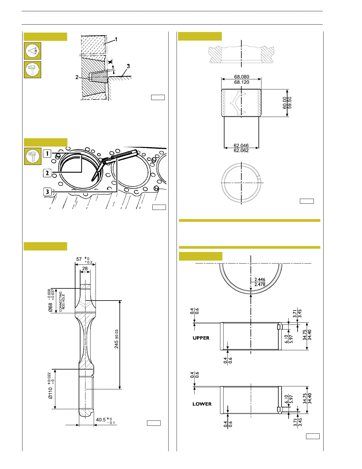
Connecting rods
CONROD BUSHING
ROD HALF (LOWER AND UPPER)
Figure 63
Figure 64
The ring (2) of the first slot has a V—shape.
The clearance ”X” between a ring and its seat is measured by
placing the piston (1), with its ring, in the cylinder liner (3) so
that the ring comes half—way out of the cylinder liner.
The upper bushing of the connecting rod cannot be
replaced.
*
3613
83434
16826
83420
82267
NOTE
30
SECTION 4 - OVERHAUL AND TECHNICAL SPECIFICATIONS
VECTOR 8 ENGINES
Base - April 2006 Print P2D32V001E
 Loading...
