Pumps & Motors
3 - 5
Introduction to Hydraulic Schematic
Symbols
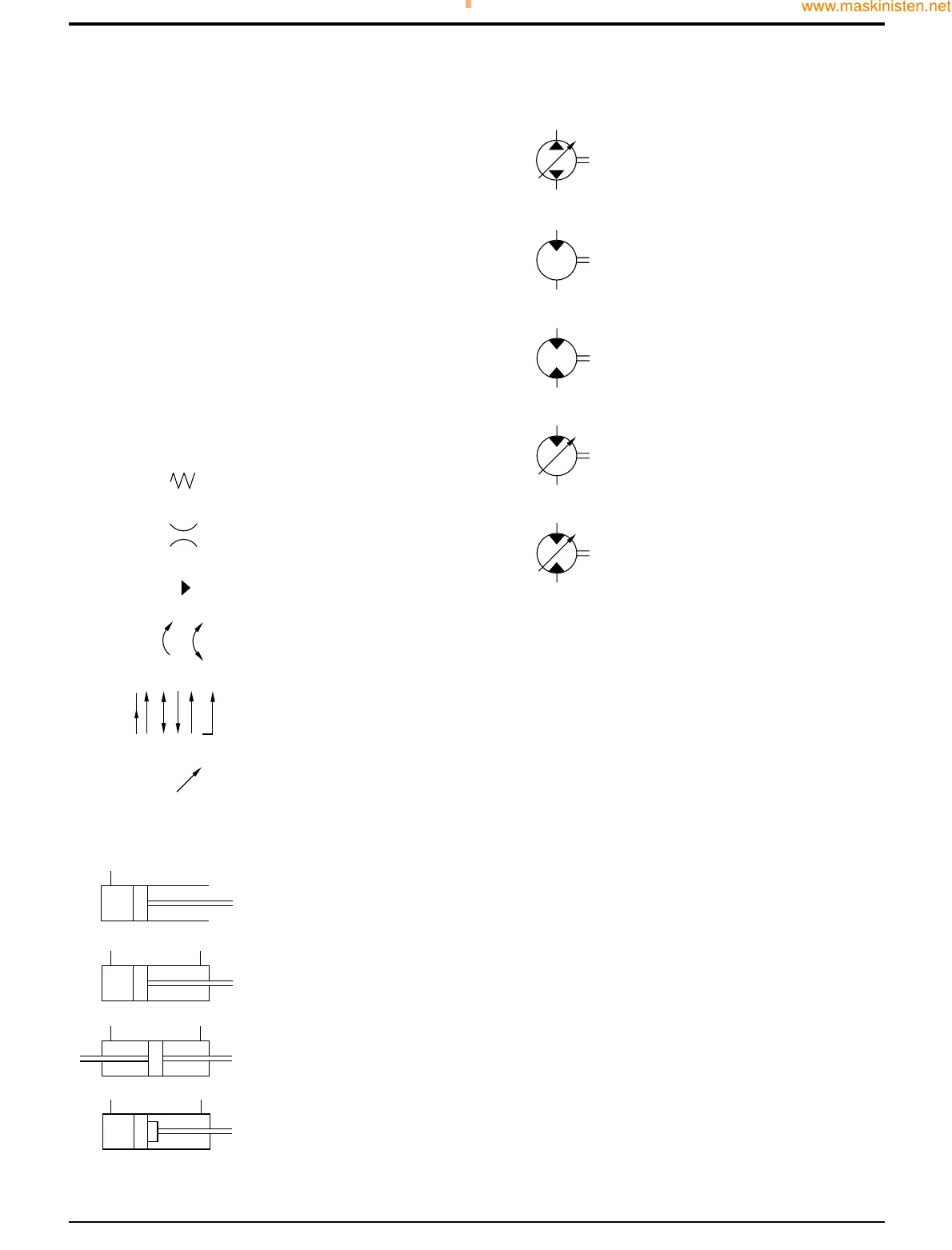
Complex hydraulic components and circuits can be
described to the engineer by using graphical symbols. The
following pages illustrate and give a brief description for
some of the more common symbols used.
There are many symbols in use and it would be impossible
to include them all here. However it should be noted that
most are only variations or refinements on the basic
principles explained here. If more detailed information is
required you are recommended to obtain a copy of BS2917
or IS01219.
Once familiar with the symbols, the engineer can use
hydraulic circuit diagrams as an aid to fault finding. It will be
possible to see the complete hydraulic circuit and decipher
the relationship between hydraulic components.
General (Basic & Functional Symbols)
Rams
Section E Hydraulics
9803/7130
Section E
3 - 5
Issue 1
Basic System Operation
A189680
A189660
A189670

 Loading...