6 - 2
Syncro Shuttle Gearbox
Synchromesh - Operation
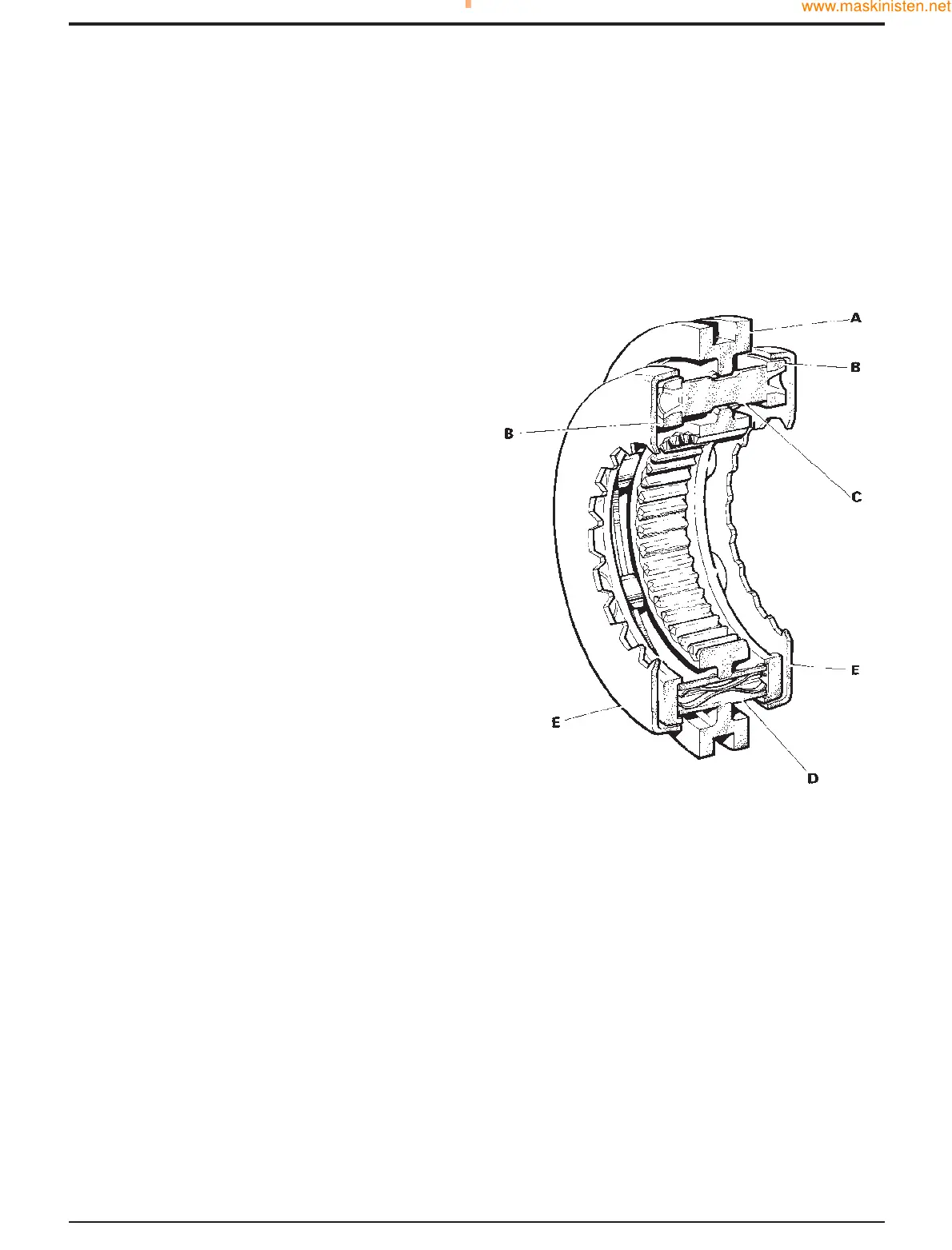
The gearbox is fitted with 'Blocking Pin' synchromesh,
comprising the following parts.
SYNCRO HUB (A) controls the operation of the
synchromesh unit and gear selection, the selector fork fitting
into the outer groove. Internal dog teeth link the selected
gear to the drive shaft. Through the syncro hub centre are
two sets of holes for the blocker pins (C) and the split
energiser pins (D), spaced alternately.
SYNCRO RINGS (B) are rigidly joined by the blocker pins,
with the split energiser pins held, in counterbores, between
the two syncro rings.
BLOCKER PINS (C) have a narrow neck in the centre,
against which the syncro hub transmits radial drive during
gear changes. The edges of the blocker pin neck and their
mating syncro hub holes are designed so that, as the radial
loads are reduced, the syncro hub can slide over the
shoulder of the blocker pin.
SPLIT ENERGISER PINS (D) take the initial axial load of the
syncro hub on the shoulder of the split energiser pin neck.
As the axial load reaches approximately 400 N (40.8 kg; 90
lb) the internal springs allow the split energiser pin to
collapse and the syncro hub to move axially.
SYNCRO CUPS (E) take the frictional drive from the syncro
ring on their inner faces. The syncro cups are splined to
drive their respective gears whilst synchronisation is taking
place.
SYNCHROMESH - OPERATION
Diagram F shows the gearbox with first gear engaged.
Syncro ring B is in contact with syncro cup E and the syncro
hub dog teeth are linking first gear to the shaft gear. In this
position the split energiser pins D are 'collapsed'.
When selecting second gear the syncro hub A slides along
the split energiser pins until the pin recess and the syncro
hub flange are in line. At this point the split energiser pins
open and the syncro rings are moved by the syncro hub
pushing on the split energiser pin shoulder.
Initial contact between the syncro ring and the syncro cup
starts to synchronise the speed of the shaft and second
gear. The rotational force of the syncro ring is taken by the
blocker pin against the edge of the syncro hub hole, as at G.
As the axial load on the syncro hub increases, the split
energiser pin 'collapses' and the conical faces of the
blocking pin and syncro hub hole come into contact, as at
H.
Further increases in the axial loads increase the frictional
grip of the syncro ring and the syncro cup, causing the shaft
and gear speeds to synchronise.
As the speeds are synchronised the radial load on the
blocker pin and the syncro hub is reduced. This allows the
syncro hub to slide freely along the blocker pin and engage
its dog teeth with second gear, see diagram J.
Section F Transmission
9803/7130
Section F
6 - 2
Issue 1
Systems Description
 Loading...