61 - 5
Assembly (Cont'd)
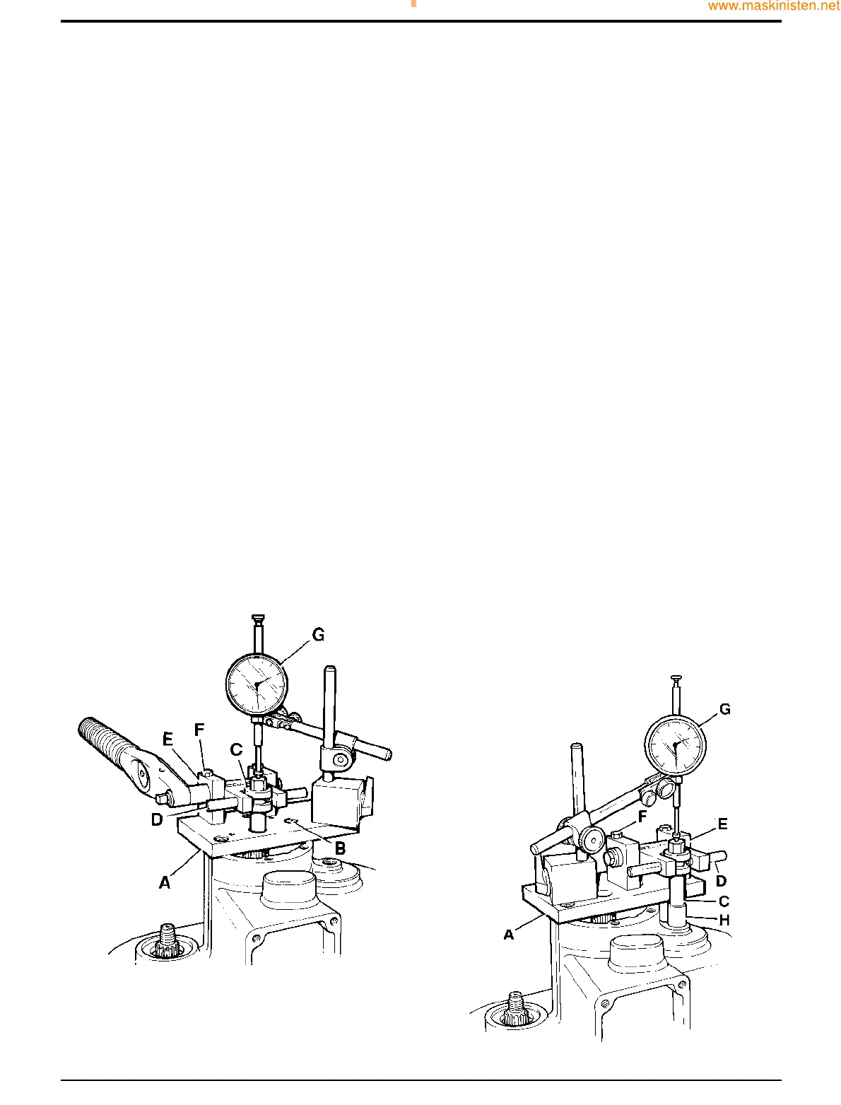
Shaft End Float Measurements
14 Clean the layshaft end cover mating face.
15 Using service tool kit 993/59400, fit base plate A onto
the layshaft end cover mating face and secure with
socket head set screws B. Torque tighten to 56 Nm
(41.3 lbf ft).
16 Pass the adaptor C through the large diameter hole in
the base plate and screw into the end of the layshaft.
17 Fit the lever arm pegs D into the adaptor annular space.
Position the lever unit mounting blocks E on the base
plate and secure with bolts F. Tighten the bolts.
18 Fit a magnetic base dial test indicator (DTI) G onto the
base plate with the pin resting on the top of the
adaptor.
19 Measure layshaft end float as follows (refer to view W):
a Using a torque spanner on the nut of the lever unit
as shown, apply a torque of 30 Nm (22.1 lbf ft)
clockwise while turning the output shaft backwards
and forwards using a turning handle. Zero the DTI.
b Apply a torque of 30 Nm (22.1 lbf ft) anti-clockwise
while turning the output shaft backwards and
forwards using a turning handle. Take the layshaft
end float reading from the DTI.
20 Calculate the required shim thickness.
Example:
a End Float Tolerance : 0.03 to 0.08 mm. (Identical
clearance for all shafts.)
b Measured End Float : 0.20 mm
c To give an end float within the tolerance, subtract
0.05mm from dimension at para. b for the required
shim thickness,
e.g., 0.20 - 0.05 = 0.15 mm.
21 Remove the bolts F securing the lever unit mounting
blocks E and remove the lever unit. Unscrew and
remove the adaptor C.
22 Remove taper plug 67.
23 Fit the short extension H to the adaptor C.
24 Using a lever, put the gearbox in gear.
25 Screw the adaptor into the end of the main shaft. Fit the
lever arm pegs D into the adaptor annular space.
Position the lever unit mounting blocks E in the
appropriate position on the base plate A and secure
with bolts F. Tighten the bolts.
26 Fit a magnetic base DTI G onto the base plate with the
pin resting on the top of the adaptor.
27 Measure main shaft end float and determine shim
thickness by repeating steps 19 and 20. Refer to view
X.
Section F Transmission
9803/7130
Section F
61 - 5
Issue 1
Syncro Shuttle Gearbox
S204020
S204030
WW
XX

 Loading...