3 - 15
Introduction to Hydraulic Schematic
Symbols (cont'd)
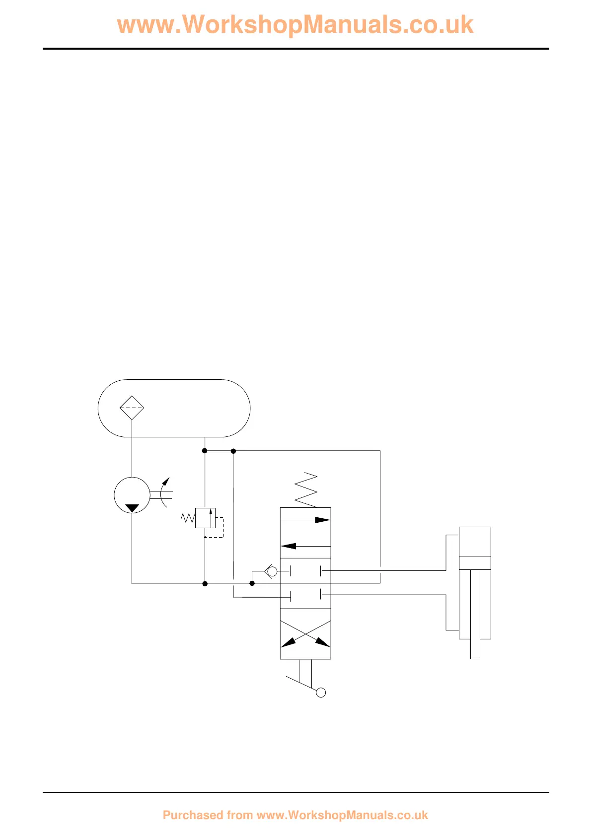
Example of Schematic Circuit
Some of the symbols described on the preceding pages
have been arranged into a simple schematic circuit shown
below.
Hydraulic tank A is a pressurised tank with an internally
mounted strainer B on the suction line to the fixed
displacement pump C. System pressure is limited to the
setting of relief valve D.
Valve spool E is an open-centre spool that is in neutral
position; flow from the pump passes through the spool and
returns to the hydraulic tank.
If the lever operated spool is moved away from neutral
position hydraulic fluid is directed to either head side or rod
side of hydraulic ram G. Notice that the fluid must first open
one way valve F before flowing to the ram.
Example Circuit Key
A Hydraulic Tank
B Strainer
C Fixed Displacement Pump
D Relief Valve
E Spool
F One Way Valve
G Double Acting Hydraulic Ram
Section E Hydraulics
9803/3280
Section E
3 - 15
Issue 1
Basic System Operation
A189770
 Loading...