33 - 2
ECU Electrical Connections
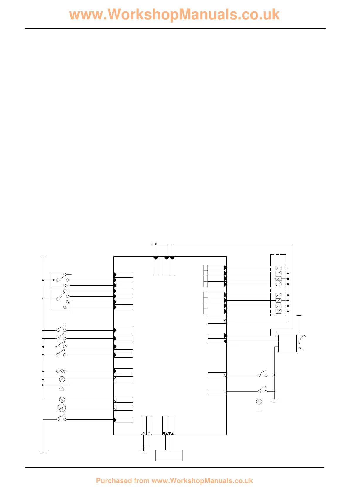
Electrical connections at the ECU are shown in the diagram
below. Connections are divided into two groups;
GB Connections to components mounted on the gearbox
GC Connections to components mounted elsewhere on the
machine.
For the key to the main components see Component
Identification on the previous page. For more detailed
explanations of the electrical connections for gearbox
control see subsequent pages.
Note: When fault finding DO NOT use a multimeter on the
ECU connector pins. Only test the associated wiring,
uncouple connectors GB and GC and then use a multimeter
at the pins inside these connectors as applicable. Use the
ShiftMaster Diagnostics system to identify possible faults
with the ECU See Powershift Gearbox - 6 Speed,
ShiftMaster Diagnostics - User Guide.
Section F Transmission
9803/3280
Section F
33 - 2
Issue 1
Electrical Connections
Powershift Gearbox - 6 Speed
GB1 Feed from GC10
GB2 12v Feed
GB4 12v Feed
GB6 Diagnostics connector
GB7 Forward switch
GB8 2nd gear switch
GB13 Warning lamp
Low trans oil pressure
GB14 Speedometer input
GB17 Auto gear switch
GB18 1st gear switch
GB19 Throttle switch
GB20 Foot brake switch
(4WD/4 wheel brake)
GB24 Diagnostics connector
GB25 Master warning lamp
GB26 ECU Earth
GB27 3rd gear switch
GB28 Neutral switch
GB30 Parkbrake ON switch
GB36 ECU Earth
GB37 Trans dump switch
GB38 Reverse switch
GB39 Kickdown switch
GB40 4WD switch
GC3 Speed sensor -
input
GC4 Output - ‘Z’ solenoid
GC6 Output - ‘U’ solenoid
GC10 Feed to GB1
GC11 Switch
Low trans oil pressure
GC12 Output - ‘X’ solenoid
GC13 ECU Earth
GC15 Output - ‘Y’ solenoid
GC18 Output - ‘S’ 4WD
solenoid
GC20 Output - ‘V’ solenoid
GC21 Switch
Trans oil temperature
GC23 Output - ‘W’ solenoid
GC24 Output - ‘T’ solenoid
 Loading...