40 - 1
Removal and Replacement
!
WARNING
Make the machine safe before getting beneath it. Lower
the attachments to the ground; engage the parking
brake; remove the starter key, disconnect the battery.
2-3-2-2
The priority valve is mounted on the right hand side chassis
member, adjacent to the loader valve block. It is attached to
the chassis member by one bolt A, and is accessible from
underneath the machine.
When replacing always renew sealing ‘O’ rings 2, 4, 6, and
10.
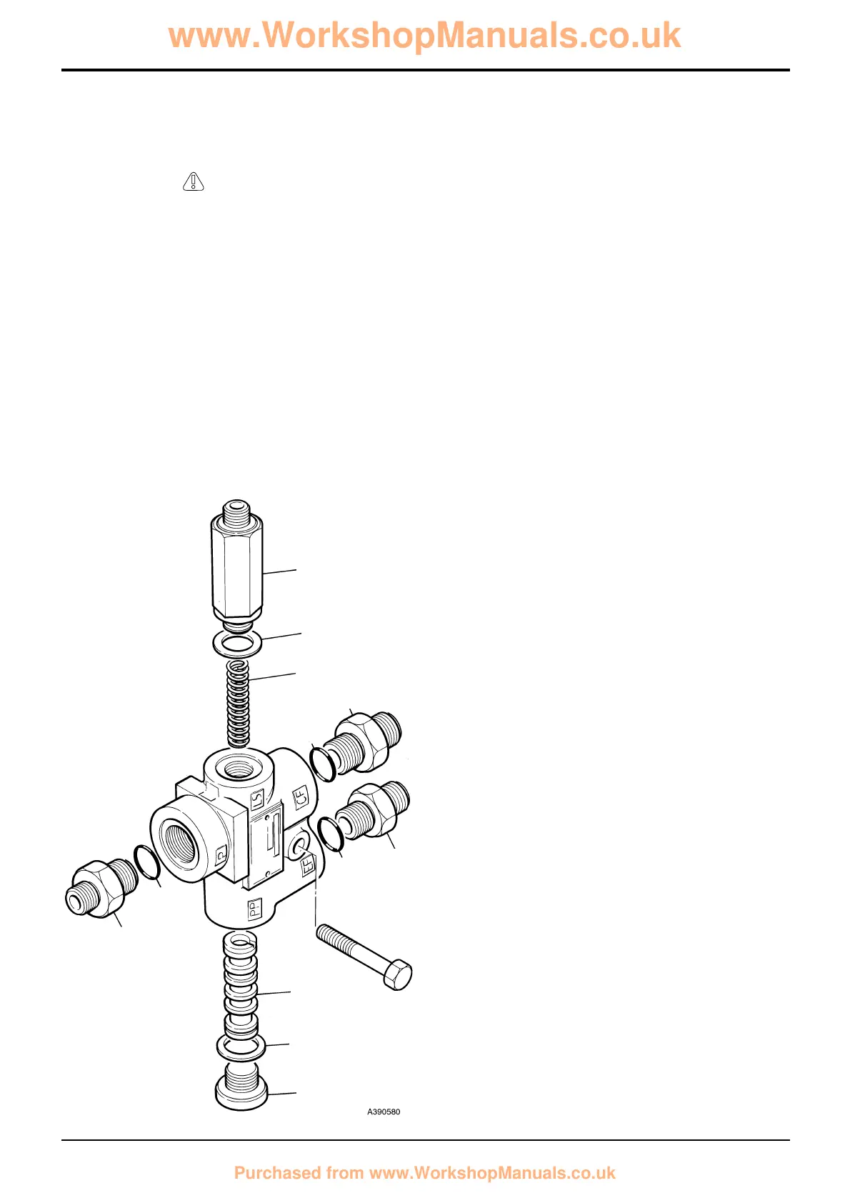
Dismantling and Assembly
The numerical sequence shown on the illustration is
intended as a guide to dismantling.
For assembly the sequence should be reversed.
Note 1: The priority valve is not serviceable beyond the
removal of foreign matter (Refer to Service Procedures,
Priority Valve - Cleaning). A faulty unit must be replaced.
Dismantling
Press out the spool item 12 using a nylon pin. Take care not
to damage the bores of the valve.
Assembly
Make sure that spring seat of spool 12 faces toward LS
connection.
Clean all parts in clean paraffin.
Lubricate all parts with hydraulic fluid.
Renew aluminium washers 8 and 10.
Note 2: All hydraulic adapters that are installed together with
a bonded sealing washer must also have JCB Threadseal
applied to the threads of the adapter.
Torque Settings
Item Nm lbf ft
7 50 37
9 50 37
Bleeding
To bleed the LS line, start the engine, loosen the connection
on the valve, turn and hold the steering wheel fully in either
direction. When bubble free oil flows from the joint, tighten
the connection.
Section H Steering
9803/3280
Section H
40 - 1
Issue 1
Priority Valve
9
10
11
1
2
3
4
12
8
7
5
6
A
 Loading...