32 - 2
Powershift Gearbox - 4 Speed (cont’d)
Electrical Connections - Quick Reference
The tables show switch positions together with energised
relay and gearbox solenoids for each gearbox function
(reverse gears are shown on the next page). The numbers
show which contacts are ‘live’ and also relate to the actual
connector pin numbers.
When fault finding it should be remembered that the system
relies on the dump switch and park brake switches
functioning correctly, failure of these switches will prevent
forward or reverse gears being selected. From the tables it is
possible to see common relay functions which can help
trace faults. For example we can see that relay FF2 is
energised to engage 1st or 2nd gear. Failure of these gears
to select may indicate a fault with relay FF2.
Note that a non functioning relay or solenoid may not
indicate a faulty component, the associated wires and
connectors may have failed. For wire and connector details
see the relevant schematic.
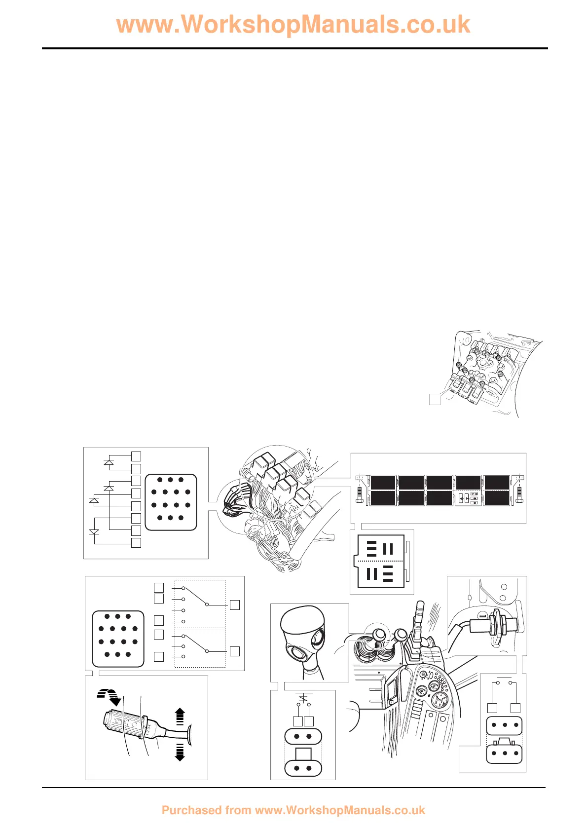
Diagram X
The diagram X (opposite) shows the electrical circuit for the
gearbox control. It is shown with 3rd gear forward selected.
‘Live feed’ wires are coloured red and feed to earth are
green.
Key
C50 Reverse alarm
DW Park brake switch
FL Column switch connector
FK Diode gate connector
FG Transmission dump relay
FD2 Forward relay
FE2 Reverse relay
FF1 Interlock relay
FD1 Forward Hi/Lo relay
FE1 Reverse Hi/Lo relay
FF2 Mainshaft/Layshaft relay
NG Dump switch
Gearbox Solenoids
T Forward low
U Forward high
Y Mainshaft
Z Layshaft
Note: Solenoid S is the
2/4WD solenoid. The 2/4WD
select electrical system is
not described in this
section.
Section F Transmission
9803/3280
Section F
32 - 2
Issue 1
Electrical Connections
 Loading...