5 - 9
Section E
Hydraulics
9803/3280
Section E
5 - 9
Issue 1
Circuit Descriptions
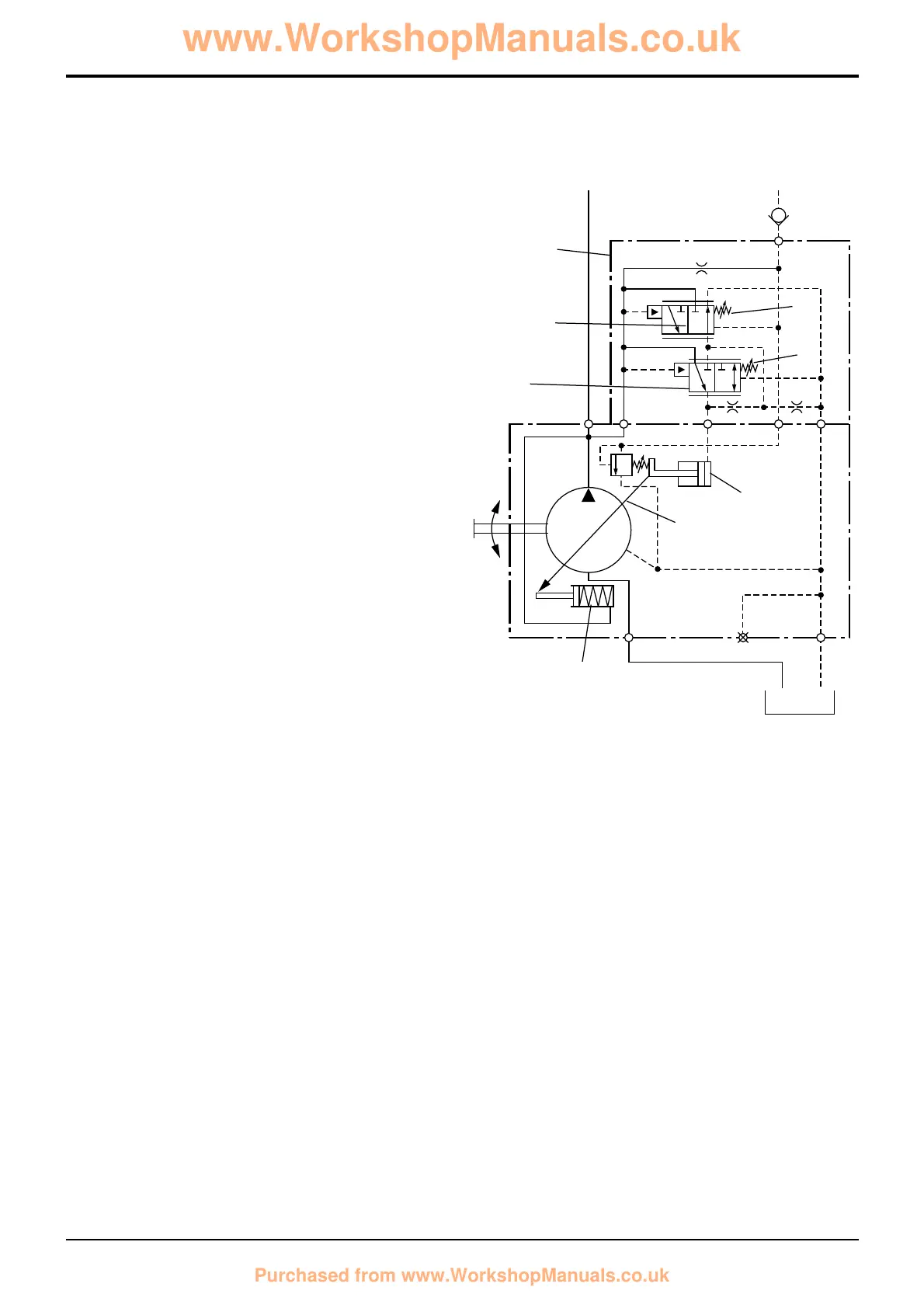
Hydraulic Pump - Variable Flow
Pressure/Flow Regulator Valve
Load Sensing - Maximum Pressure (no flow)
When a service ram reaches the end of its stroke or the
service meets resistance (for instance tearing out), the signal
pressure from the loader (or backhoe) valve 13 will increase
to the same pressure as pump output pressure.
The force of spring 6 is sufficient to move spool 4 down. The
pressure in the system is also sufficient to move spool 3 up
against the force of spring 12, this creates a connection from
the pump outlet to control piston 7 via port A.
Control piston 7 moves thus decreasing the angle of
swashplate 2. Pump output flow now decreases whilst the
system pressure is maintained at maximum setting. There is
now no flow but maximum system pressure.
 Loading...