62 - 23
Section E
Hydraulics
9803/3280
Section E
62 - 23
Issue 1
Excavator Valve
Assembly
Assembly is the reverse of the dismantling sequence.
1 Clean the valve components in an appropriate solvent.
2 Renew all 'O' rings and back-up rings.
3 Lubricate parts with JCB Hydraulic Fluid before
assembling. Make sure that all the parts move freely.
4 Adjust the pressure setting as required. Refer to
Service Procedures, Pressure Testing, Load Sense
Relief Valve.
Dismantling and Assembly
Precision Control (Servo)
(Machines from January 2003)
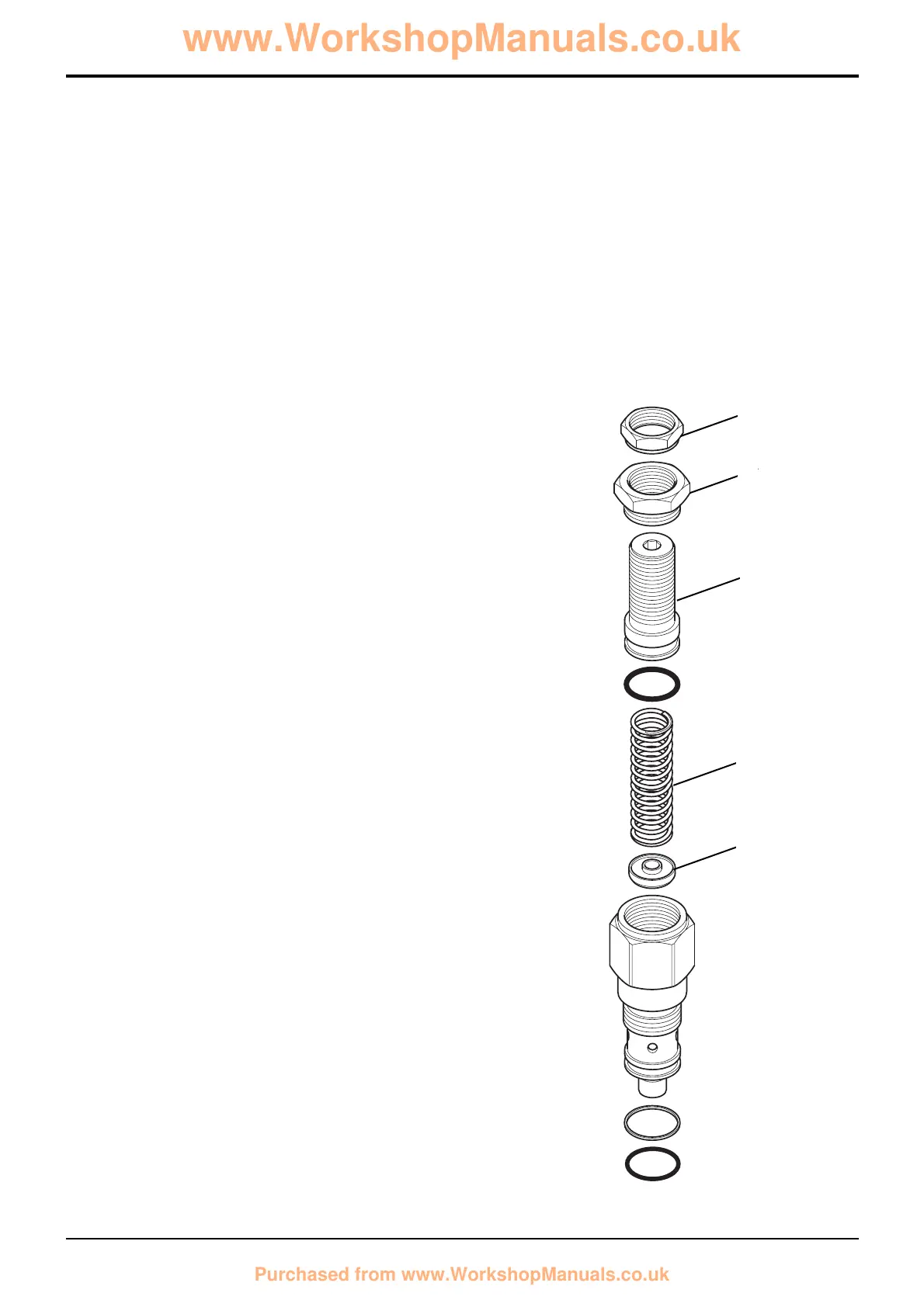
Load Sense Relief Valve
Removal
It is possible to remove a valve without removing the
excavator valve block from the machine.
Note: If removing components from a valve block that is
fitted on a machine the pilot circuit accumulator pressure
must be vented first. With the operator seat locked in the
rear facing position and with the arm rests raised forward (for
backhoe operation), switch the starter to ON without starting
the engine. Operate the joystick controls several times to
vent the hydraulic pressure from the servo system and
backhoe rams. Turn the starter switch to the OFF position
and remove the key.
1 Gain access to the excavator valve and disconnect and
blank any hoses or pipes which may interfere with the
removal of the load sense relief valve.
2 Unscrew the load sense relief valve from the excavator
valve block. Cover the ports to prevent the ingress of
dirt and remove to a clean working area.
Dismantling
Great care should be taken when dismantling and
assembling a valve to avoid the following:-
• Contamination
• Damage to spools
• Damage to seal grooves
Any of the above may result in possible problems with the
operation of the valve.
1 Loosen locknut 1, unscrew and remove adjuster nut 2
and adjuster screw 3.
2 Carefully remove spring 4 and poppet 5 from valve
body.
Note: When removing 'O' Rings and seals, use an
appropriatly rounded tool that WILL NOT cause any damage
to the seal grooves.
Discard ALL 'O' Rings and back-up rings. DO NOT use worn
or damaged items.
Inspection
1 Inspect the valve components for scratches, pitting,
corrosion or any other type of damage.
Note: If any part other than ‘O’ rings are damaged the entire
valve must be renewed.
1
2
3
4
5
 Loading...