Powershift Gearbox - 4 Speed
(Machines up to 933756)
Electrical Connections - Wires and Connectors
Although the system is straight forward in design it is never
the less fairly complex in practice. For this reason
schematics are divided into 2 parts: Relay Actuation and
Gearbox Solenoid Actuation.
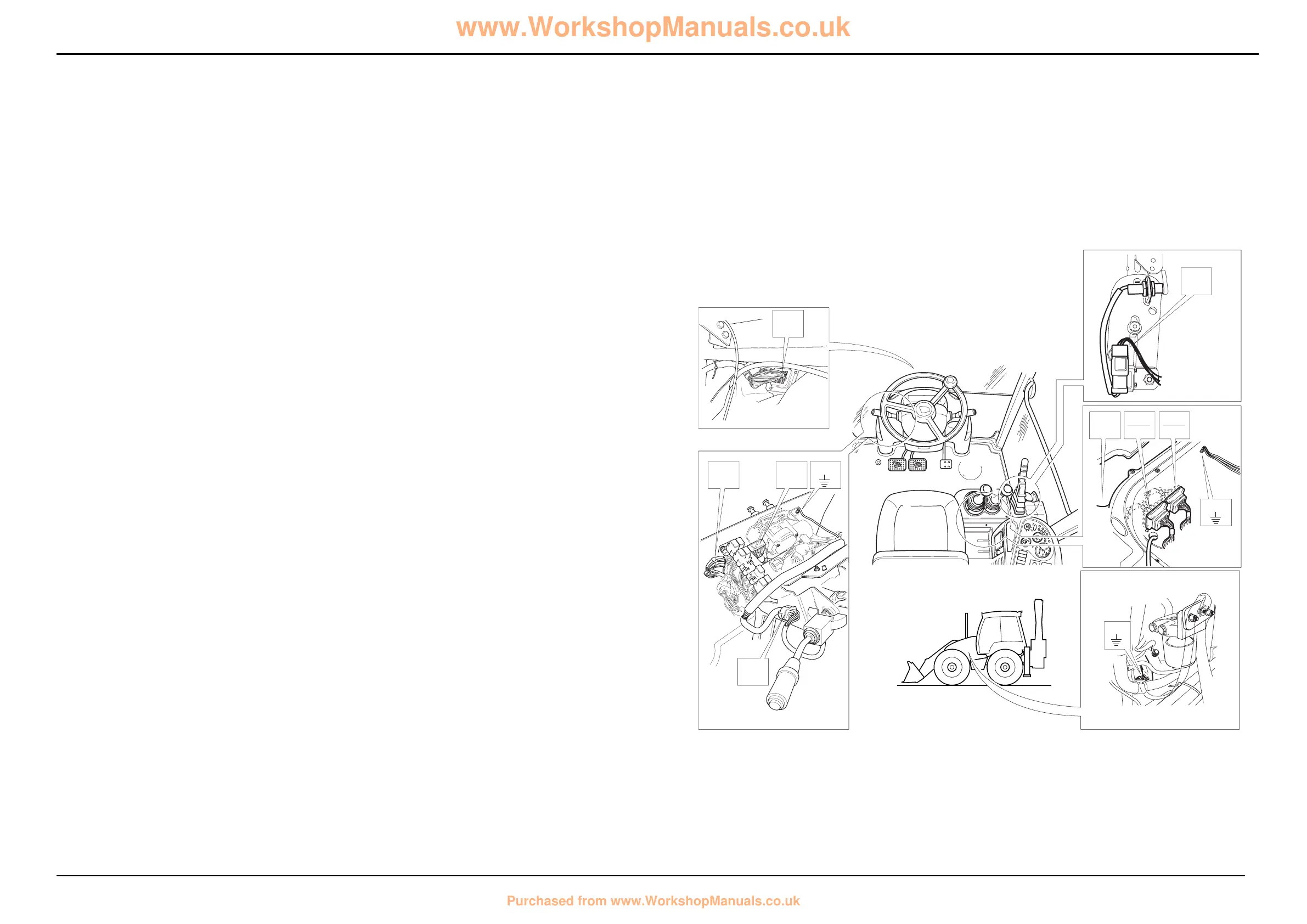
On the electrical diagram opposite the electrical connectors
(example, FA to LA) are shown looking on the mating face of
each connector when they are disconnected.
The wire numbers and colours, where appropriate, are
shown as an aid to identification whilst fault finding.
Before fault finding make sure that you understand how the
the electrical circuits work. Most potential faults can be
traced using a multimeter to carry out continuity checks on
wires, switches and soleniod coils. Gearbox solenoid coils
can be checked for the correct resistance value as given in
Technical Data. See Service Procedures, Electrical
Testing Methods for more details.
Relay Actuation
For gearbox solenoid actuation see subsequent pages.
Component Key (Relay actuation):
The following key identifies the component connectors on
the opposite diagrams. Note that the wires coloured red
show the electrical ‘live feed’ to the column gear lever.
h1 Harness - 721/10940 Front console
h2 Harness - 721/10942 Link
h3 Harness - 721/10936 Side console
h4 Harness - 721/10935 Engine/mainframe
Note: For harness drawings see Section C.
Connectors (h1)
FA h1 î h2
FB1 Earth point
FD1 Forward high/low relay
FD2 Forward relay
FE1 Reverse high/low relay
FE2 Reverse relay
FF1 Interlock relay
FF2 Mainshaft/layshaft relay
FG Transmission dump relay
FK Diode gate
FL Column gear lever
Connectors (h2)
LA h2
î h1
LB h2 î h3
Connectors (h3)
CA h3 î h4
CB h3 î h2
CCA Fuses
CCB Fuses
CM Park brake relay
DW Park brake switch
EA Immobiliser
EAB Link - immobiliser (if immobiliser is not fitted)
Connectors (h4)
NH h4 î h3
NG Transmission dump switch
MB1 Earth point
Splices (h1)
SL
SC
SG
SH
SK
SS
ST
Splices h2
SA
SB
Splices h3
SC
Splices h4
SA
Earth Points
Faults may be caused by poor earth connections. Although
earth connections are shown opposite, it must be
remembered that the cab assembly is earthed via further
earth strap and cable connections. For details of these
connections see Section C, Machine Earth Connections.
 Loading...