20 - 1
Section F Transmission
9803/3280
Section F
20 - 1
Issue 1
Basic Operation
Torque Converter
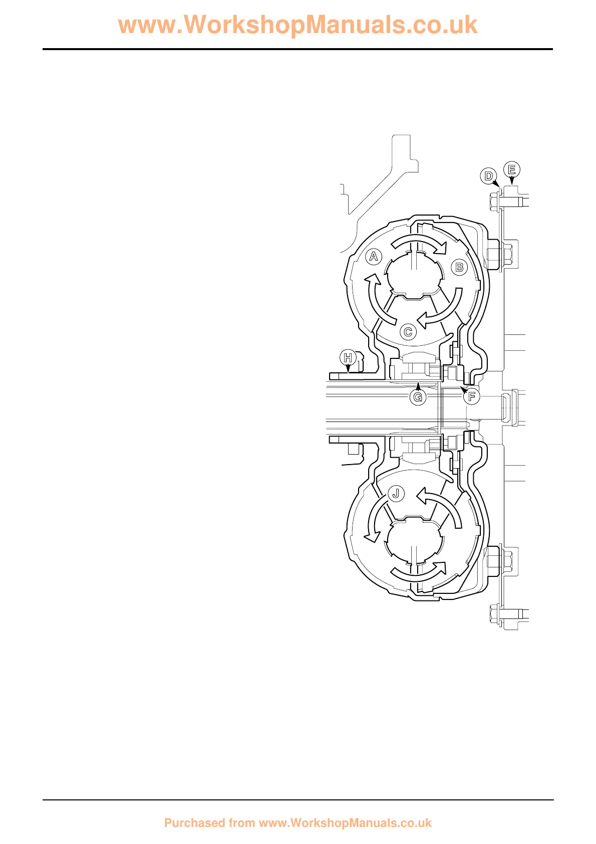
Component Identification
A Impeller
B Turbine
C Reaction member
D Drive plate
E Engine flywheel
F Drive to gearbox input shaft
G Spline location for reaction member
H Direct drive from the engine to the gearbox oil pump
J Direction of oil flow
Principle of Operation
The torque converter is similar to a fluid coupling, which
utilises the centrifugal force exerted in the transmission oil to
transmit power from the engine to the gearbox. It multiplies
the torque from the engine and functions as a combined
clutch and infinitely variable reduction gearbox
The torque converter is enclosed in a casing and consists of
three basic parts, the impeller A, reaction member C, and
turbine B.
Impeller A is driven by the engine.
Reaction member C does not rotate. Its hub engages with a
splined tube on the gearbox oil pump and is held stationary.
Turbine B is engaged with the splined end of the gearbox
input shaft.
The impeller A, driven by the engine, forms one set of
shaped blades, it can be likened to a centrifugal pump
imparting energy to the transmission oil. This energy is
transferred to another set of shaped blades, which form the
turbine B The turbine is connected to the gearbox and
converts the energy back to a mechanical torque.
When the impeller A is rotating faster than the turbine B, the
fixed reaction member C causes some of the energy in the
oil to be transferred back to the impeller A. This has the
effect of multiplying the torque available.
When the impeller A (input) is running much faster than the
turbine B (output) there is a substantial circulation of
transmission oil around the blades. The oil circulation is
maximum when the turbine (output) is stalled, and is almost
zero when the impeller and turbine speeds are equal i.e. the
ratio is near 1:1. If the turbine (output) is stalled whilst the
impeller (input) is revolving, all the power is dissipated as
heat.
Because of the absence of a direct mechanical connection
between the engine and the gearbox therefore, the flexibility
of the torque converter drive greatly reduces wear on the
transmission, absorbing shocks and torsional vibration from
the engine. The engine cannot be stalled due to overload, as
the fluid coupling slips.
 Loading...