– 2 –
2. INSTALLATION
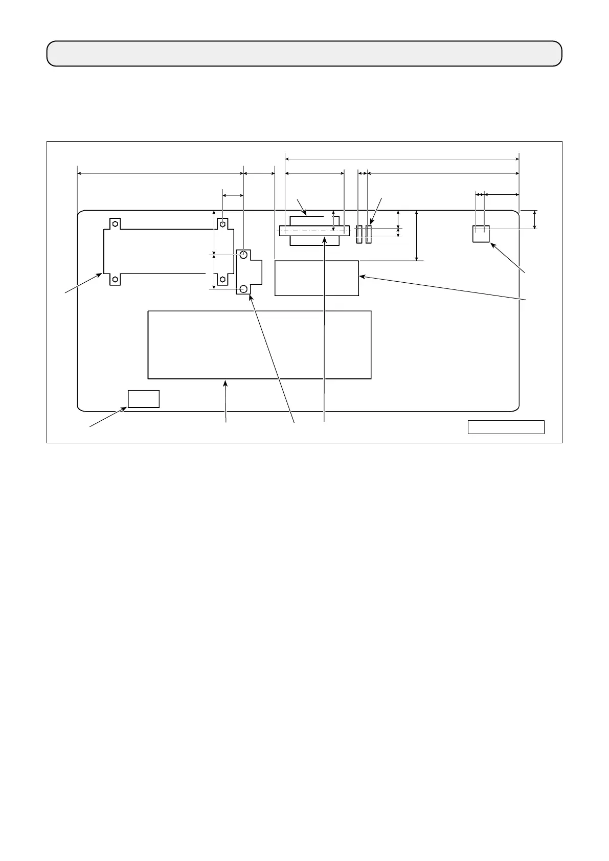
2-1. Mounting positions of the devices and table
The devices including the oil pan and electrical box are to be mounted to the positions as shown in the gure
below.
❶
Control box
❷
Power switch
❸
Oil pan
❹
Pedal sensor
❺
*2
Control box for stitch skipping detecting device
❻
*2
Solenoid valve
❼
*2
Regulator
❽
*1
Reactor box
❾
*2
DIN rail
*1: Only for the EU type models
*2: Only for the models provided with the stitch skipping detecting device and bobbin-thread remaining amount
detecting device
* Dimensions are the reference values.
Dimension: mm
❶
❷
❸
❹
❺
*2
❻
*2
❼
*2
❽
*1
40
38
30
220
105
145
352
80
175
650
62
513
58
94
110
55
❾
*2

 Loading...