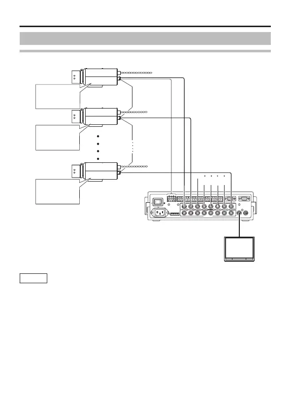
System Connection
Connection Diagram
.
1
TO CAMERA DATA I / O
RX
+
RX
-
TX
+
TX
-
COM
1 2 3 4 5 6 7 8
COM
9/1 10/2 11/3 12/4 13/5 14/6 15/7 16/8
COM COM COM
CAMERA
SW
UNIT
ALARM
AUTO
431 2 875 6
2 3 4 5 6 7
8
1
MONITOR
OUTPUT
MONITOR
SERIAL-2SERIAL-1
VIDEO INPUT
VIDEO OUTPUT
OUTPUT
2
1
ON
2 3 4 5 6 7
8
ALC
LEVEL
Av Pk
L H
ALC
LEVEL
Av Pk
L H
ALC
LEVEL
Av Pk
L H
MACHINE ID : 1
(MENU Screen)
RX TERM : OFF
(Switch)
MACHINE ID : 2
(MENU Screen)
RX TERM : OFF
(Switch)
MACHINE ID : 8
(MENU Screen)
RX TERM : ON
(Switch)
RM-P2580
CAMERA1
CAMERA2
CAMERA8
Monitor
Video signal cable
Control signal
cable
Power cable
Memo
v
During control using RM-P2580, select “JCCP” for the
[COMMUNICATION] item on the [MAINTENANCE] screen. On
the [COMMUNICATION (JCCP)] screen, set [PROTOCOL 1] to
“MULTIDROP”, and [PROTOCOL 2] to “DUPLEX”.
v
For control using a device other than RM-P2580, perform
setting using the switches and menu screen according to the
system in use.
v
For systems using RM-P2580, multiple cameras (up to 16 units)
are connected using a set of control signal cables. As such, the
entire system will not function properly if the switch setting for
any one of the connected cameras is incorrect. "Control Signal
Cable Connection on Camera (Rear)" (A page 19)
Connection/Installation
E-18
 Loading...