4 Installation and Connection
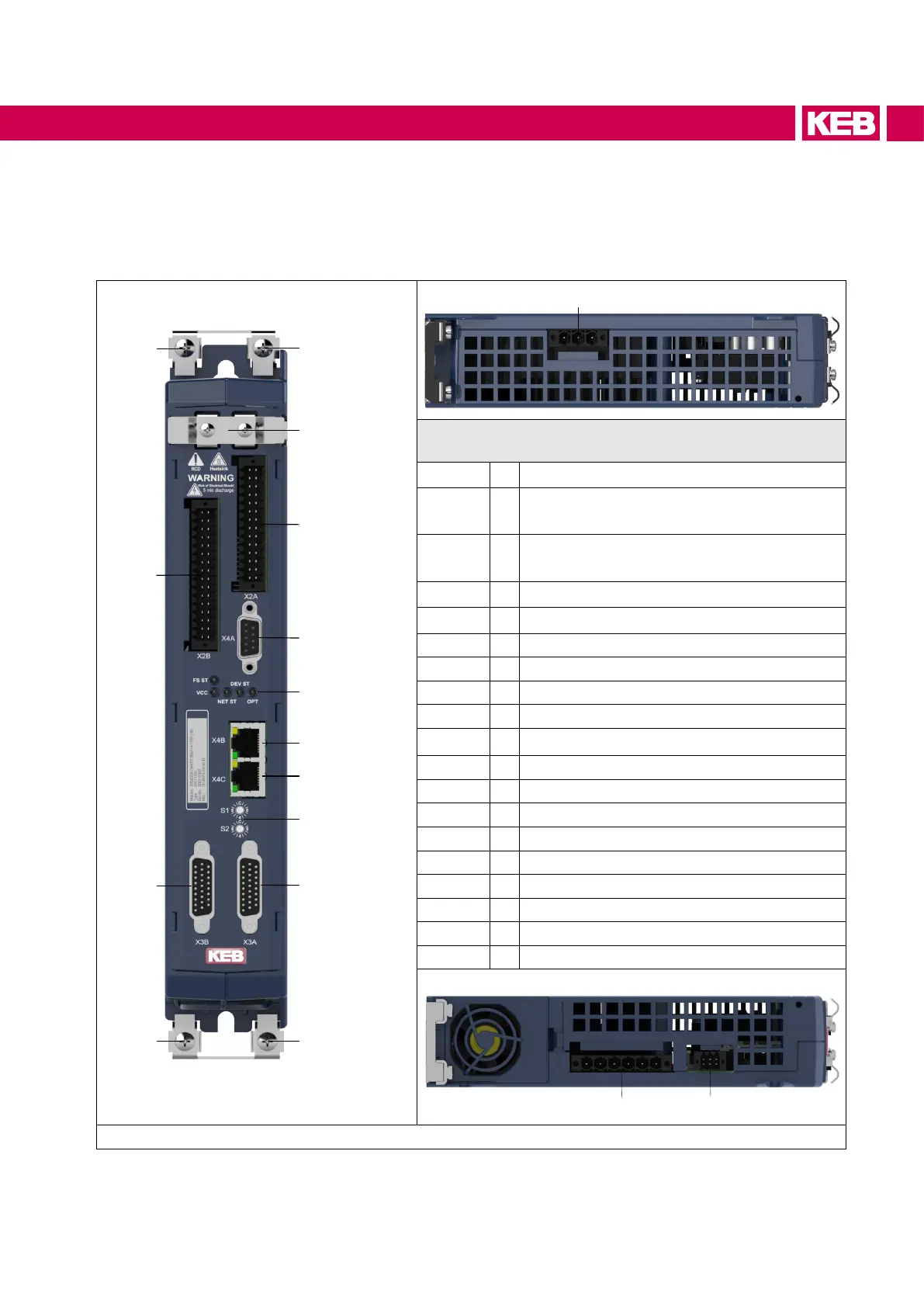
4.1 Overview of the COMBIVERT S6
PE
X2B
PE
X3B
PE
X2A
X4A
LED1...5
X4B
X4C
X3A
PE
X2Z
S1/S2
Representation by the example of an
APPLICATION control board
X1A Mains input
X1B
Motor output /
Connection for braking resistor
X1C
Temperature monitoring,
brake control
X2Z Strain relief
X2A
1)
Control terminal block
X2B
1)
Safety functions / DC 24 V supply
X2C
1)
CAN bus / analog inputs and outputs
X3A
1)
Encoder interface channel A
X3B
1)
Encoder interface channel B
X4A
1)
Diagnostic interface
X4B
1)
Fieldbus interface (in)
X4C
1)
Fieldbus interface (out)
PE Protective /functional earth
S1 / S2
1)
Rotary coding switch
FS ST
1)
Safety status
VCC
1)
Voltage supply
NET ST
1)
Fieldbus state
DEV ST
1)
Drive controller state
OPT
1)
Optional
Figure 11: Overview COMBIVERT S6
1)
Is described in the installation manual of the control board.
51
INSTALLATION AND CONNECTION

 Loading...


