59
CONNECTION OF THE POWER UNIT
4.2.4.3 Supply cable
The conductor cross-section of the supply line is determined by the following factors:
• Input current of the drive controller
• Used cable type
• Installation method and ambient temperature
• The locally valid electrical regulations
The project engineer is responsible for the design!
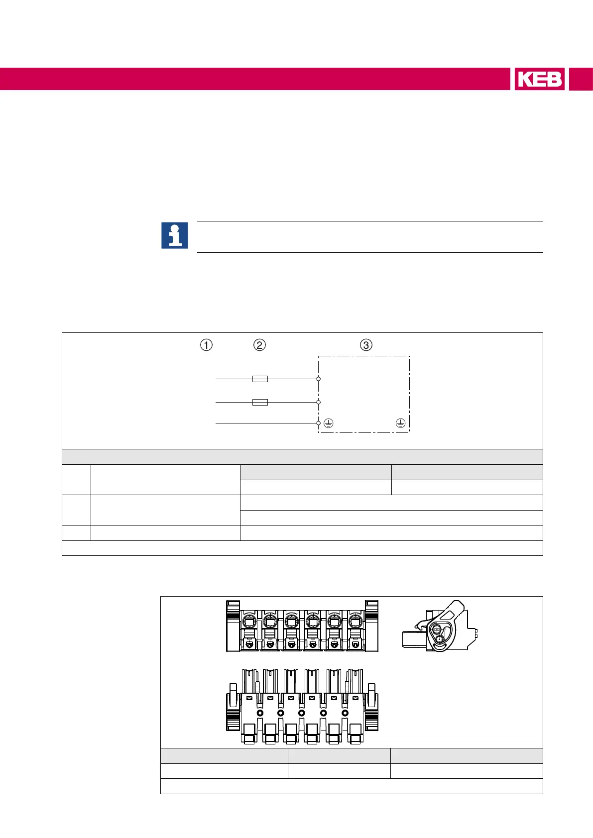
4.2.5 DC connection
4.2.5.1 Connection at DC voltage supply
- -
U
V
W
PE
TA1 TA2
++
+U
-U
Legend
1 DC voltage
230 V devices 400 V devices
260...375 V 260…750 V
2 Fuses
Type aR
Pay attention to the permissible voltage range !
3 KEB COMBIVERT S6
Figure 18: Connection at DC voltage supply
4.2.5.2 Terminal block X1B DC connection
R
W
- - ++ VU
Name Function Cross-section
++, -- DC connection 0.5...2.5 mm² / AWG 20-14
Figure 19: Terminal block X1B DC connection

 Loading...


