7½ Digit Graphical Sampling Multimeter Calibration Manual Section 2:
DMM7510-905-01 Rev. A / April 2015 2-37
3. On the Model DMM7510, press the FUNCTION key and select Temperature.
4. Press the MENU key. Under Measure, select Settings.
5. Select Transducer.
6. Set the Type to either 4-wire RTD or 3-Wire RTD.
7. Set the RTD Type to PT100.
8. Press the HOME key.
9. On the calibrator, select 19 Ω source resistance
10. Select the OPER and EX SNS keys.
11. Record Model DMM7510 accuracies.
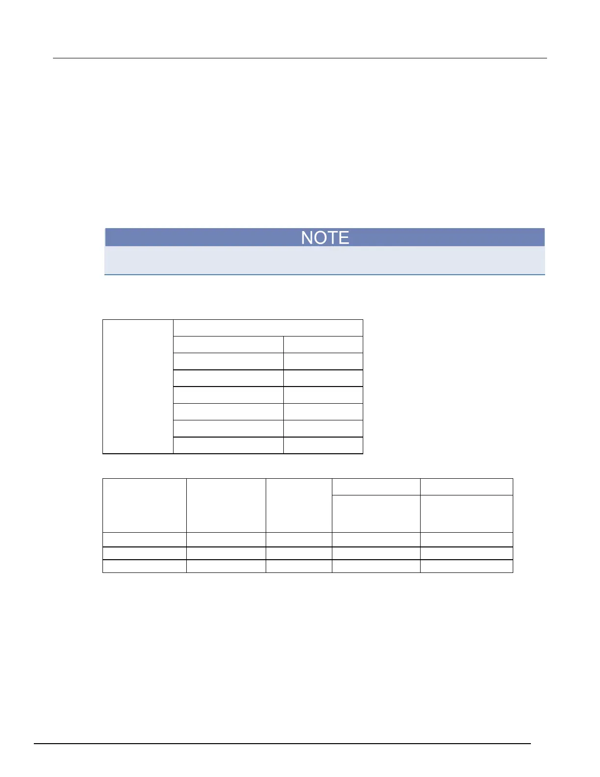
12. Refer to the table for PT100 accuracies.
Fluke 5720 and 5730 resistance source values vary and may require new resistance-to-temperature
target accuracy values.
13. Repeat for 100 Ω and 190 Ω source values.
Example
PT100
Ro
alpha
beta
delta
A
B
-5.775440E-07
C
-4.182852E-12
value
(Ω)
Actual calibrator
value
(Ω)
Temperature
(°C)
4-wire RTD 3-wire RTD
±0.06 °C accuracy
(±Ω from actual
calibrator value)
±0.75 °C accuracy
(±Ω from actual
calibrator value)
Dry circuit resistance verification
To check the dry circuit resistance function, you will:
• Use shielded, Teflon-insulated or equivalent cables in a 4-wire configuration
• Characterize the calibrator 1 Ω and 10 Ω nominal values with the external reference DMM
• Verify that the displayed readings fall within specified limits
For the 1 Ω and 10 Ω ranges, verify accuracy from the reference DMM readings
For the 100 Ω to 10 kΩ ranges, verify accuracy from actual calibrator source values

 Loading...


