2-7
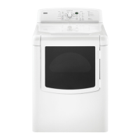
Put power supply cord through the strain
relief. Be sure that the wire insulation on
the power supply cord is inside the strain
relief. The strain relief should have a tight
fit with the dryer cabinet and be in a hori
-
zontal position. Do not further tighten strain
relief screws at this point.
•
4. Now complete installation following in-
structions for your type of electrical con
-
nection:
4-wire (recommended)
3-wire (if 4-wire is not available)
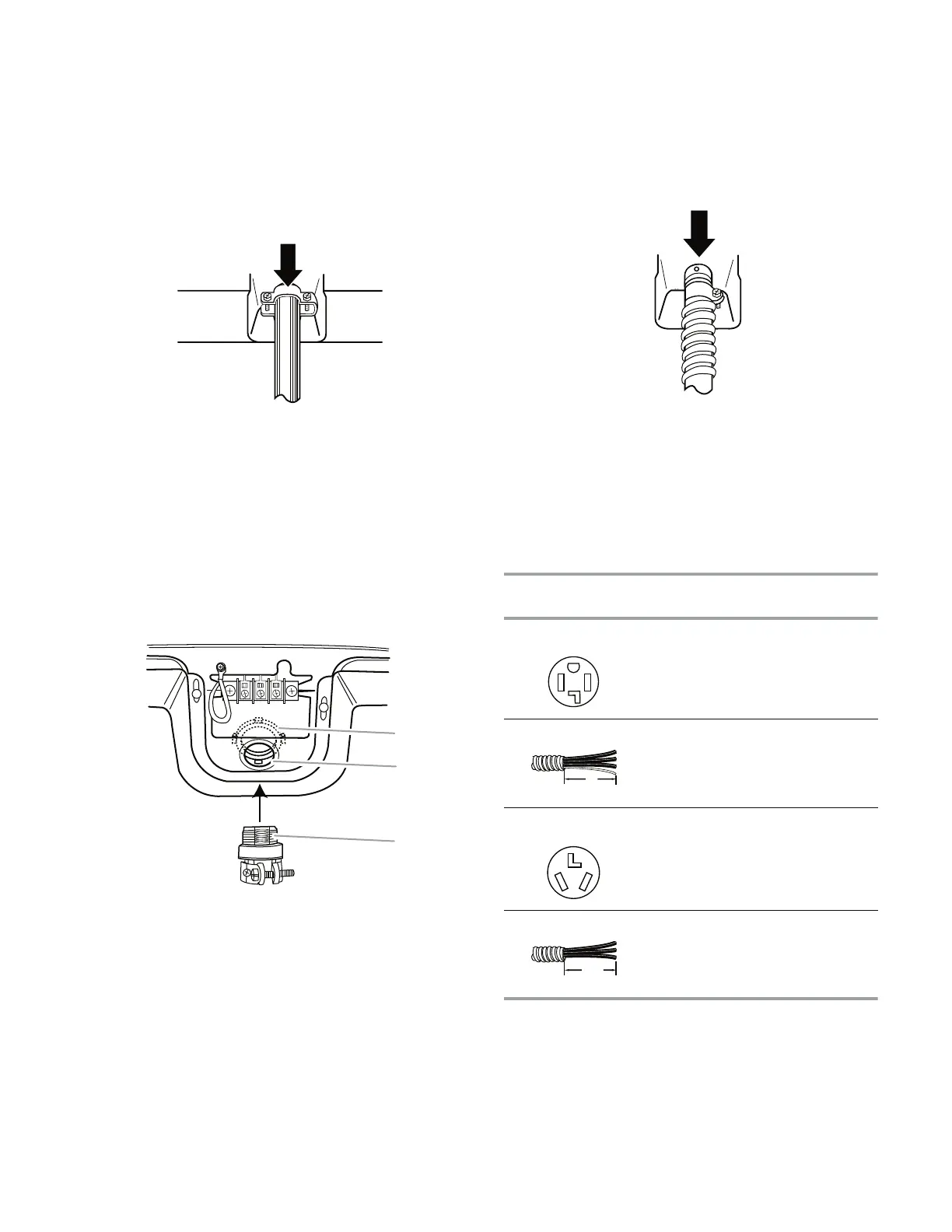
Electrical Connection Options
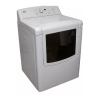
Style 2: Direct wire strain relief
Unscrew the removable conduit connector
and any screws from a 3/4
˝ (1.9 cm) UL
listed strain relief (UL marking on strain re
-
lief). Put the threaded section of the strain
relief through the hole below the terminal
block opening. Reaching inside the termi-
nal block opening, screw the removable
conduit connector onto the strain relief
threads.
•
A. Removable conduit connector
B. Hole below terminal block openin
g
C. Strain relief thread
s
B
C
A
Put direct wire cable through the strain re-
lief. The strain relief should have a tight fit
with the dryer cabinet and be in a horizontal
position. Tighten strain relief screw against
the direct wire cable.
•
* If local codes do not permit the connection of a cabinet-ground
conductor to the neutral wire, go to
“Optional 3-wire connection”
section
.
If your home has
And you will be
connecting to:
Go to Section:
4-wire receptacle
(NEMA type 14-30R)
A UL listed,
120/240-volt
minimum,
30-amp, dryer
power supply
cord
*
4-wire connection:
Power Supply
Cord
4-wire direct
disconnect or
circuit breaker
box*
4-wire connection
:
Direct Wire
3-wire receptacle
(NEMA type 10-30R)
A UL listed,
120/240-volt
minimum,
30-amp, dryer
power supply
cord
*
3-wire connection
:
Power Supply
Cord
3-wire direct
A fused
A fused
disc
onnect or
circuit breaker
box*
3-wire connection
:
Direct Wire
(12.7 cm)
5"
(8.9 cm)
3
¹⁄2
"
 Loading...