2-19
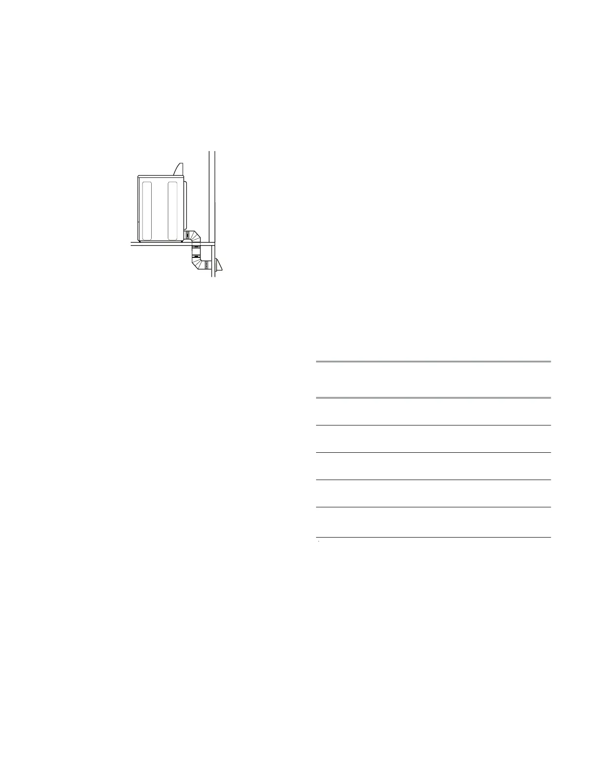
Determine vent path
Select the route that will provide the
straightest and most direct path outdoors.
Plan the installation to use the fewest num-
ber of elbows and turns.
When using elbows or making turns, allow
as much room as possible.
Bend vent gradually to avoid kinking.
Use the fewest 90° turns possible.
Determine vent length and elbows needed
for best drying performance
Use the following Vent system chart to
determine type of vent material and hood
combinations acceptable to use.
•
•
•
•
•
•
Number of
90º turns
or elbows
Type of
vent
Box or
Louver
ed
hoods
Angled
hoods
0 Rigid meta
l
Flexible meta
l
64 ft (20 m)
36 ft (11 m)
58
ft (17.7 m)
28 ft (8.5 m)
1 Rigid meta
l
Flexible meta
l
54
ft (16.5 m)
31 ft (9.4 m)
48 ft (14.6 m)
23 ft (7 m)
2 Rigid metal
Flexible meta
l
44 ft (13.4 m)
27 ft (8.2 m)
38
ft (11.6 m)
19 ft (5.8 m)
3 Rigid meta
l
Flexible meta
l
35 ft (10.7 m)
25 ft (7.6 m)
29 ft (8.8 m)
17 ft (5.2 m)
4 Rigid meta
l
Flexible meta
l
27 ft (8.2 m)
23 ft (7 m)
21 ft (6.4 m)
15 ft (4.6 m)
Special provisions for mobile home instal-
lations
The exhaust vent must be securely fastened to
a noncombustible portion of the mobile home
structure and must not terminate beneath the
mobile home. Terminate the exhaust vent out-
side.
NOTE: Do not use vent runs longer than
those specified in the Vent system chart.
Exhaust systems longer than those speci
-
fied will:
Shorten the life of the dryer.
Reduce performance, resulting in longer
drying times and increased energy us
-
age.
The Vent system chart provides venting re
-
quirements that will help to achieve the best
drying performance.
Vent system chart
NOTE: Bottom exhaust performance is equiv-
alent to adding two elbows. To determine
maximum exhaust length, add two elbows to
the chart.
NOTE: Performance of rear exhaust to ei-
ther side of the dryer is equivalent to adding
one elbow. To determine maximum exhaust
length, add one elbow to the chart.
•
•
 Loading...