6-9
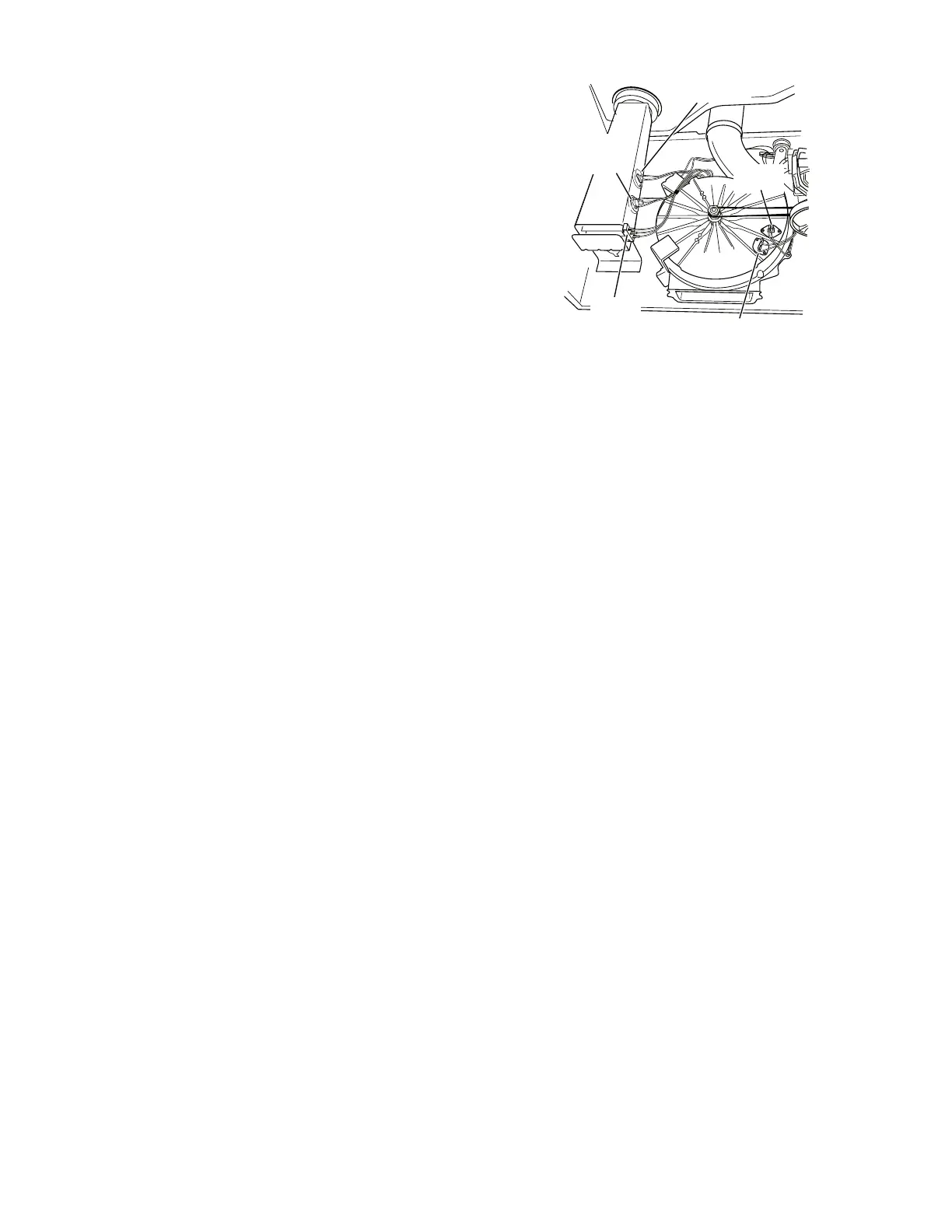
Thermal Fuse
Exhaust
Thermistor
Inlet Thermistor/
High Limit
Thermostat
Thermal Cut-Off
Heater
Element
Figure 10. Thermal components, viewed
from front.
4. Visually check the wire connections to
the thermal cut-off, high limit thermostat,
and heater. If connections look good,
check for continuity across each of these
components.
Replace the heater if it is electrically
open.
Replace both the thermal cut-off and
high limit thermostat if either one is
electrically open.
5. If no open circuit is detected, remove the
P4 connector, then measure the resis-
tance between P4-3 (red wire) and P4-6
(red wire) at the connector. See Figure 16,
for connector location; and Accessing &
Removing the Electronic Assemblies.
If 5–15 k ohms are measured, replace
the machine control electronics.
If the resistance is less than 1 k ohm,
replace the thermistor.
•
•
•
•
TEST #4 Heater
This test is performed when either of the fol-
lowing situations occur:
Dryer does not heat
Heat will not shut off
This test checks the components making up
the heating circuit. The following items are
part of this system:
Harness/connection
Heater relay
Thermal cut-off
Inlet thermistor/high limit thermostat
Heat element assembly
Centrifugal switch
Exhaust thermistor
Machine control electronics. See ESD
information
User interface assembly
Dryer does not heat:
Locate the components using Figure 1 and
Figure 10.
SINGLE ELEMENT MODEL:
1. Unplug dryer or disconnect power.
2. Remove the front panel and drum assem-
bly to access the thermal components.
See Removing the Front Panel/Drum As
-
sembly.
3. Using an ohmmeter and referring to the
appropriate wiring diagram and strip cir
-
cuit (see Section 7), measure the resis
-
tance from the red wire at the thermal
cut-off to the red wire at the heater.
If the resistance is about 10 ohms, go
to step 5.
If an open circuit is detected, go to
step 4.
•
•
•
•
•
•
•
•
•
•
•
•
•
 Loading...