CONTROLS
AND INDICATORS
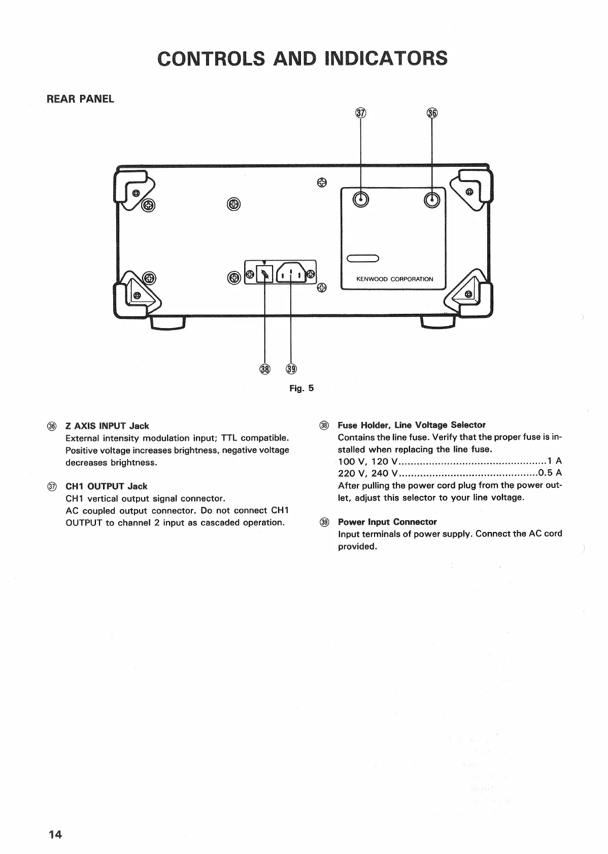
REAR
PANEL
Fig.
5
(§)
Z AXIS INPUT
Jack
External
intensity modulation
input;
TTL compatible.
Positive
voltage
increases
brightness, negative voltage
decreases
brightness.
© CH1 OUTPUT
Jack
CH1
vertical
output
signal connector.
AC
coupled
output
connector. Do not connect CH1
OUTPUT
to channel 2
input
as cascaded operation.
(§)
Fuse
Holder, Line Voltage Selector
Contains
the line
fuse.
Verify that the proper fuse is in-
stalled
when replacing the line
fuse.
100
V, 120 V 1 A
220
V, 240 V.
....0.5
A
After
pulling
the power cord plug
from
the power
out-
let, adjust this selector to your line voltage.
(§) Power Input Connector
Input terminals of power supply. Connect the AC cord
provided.
14

 Loading...


