OPERATING
INSTRUCTIONS
INITIAL STARTING
PROCEDURE
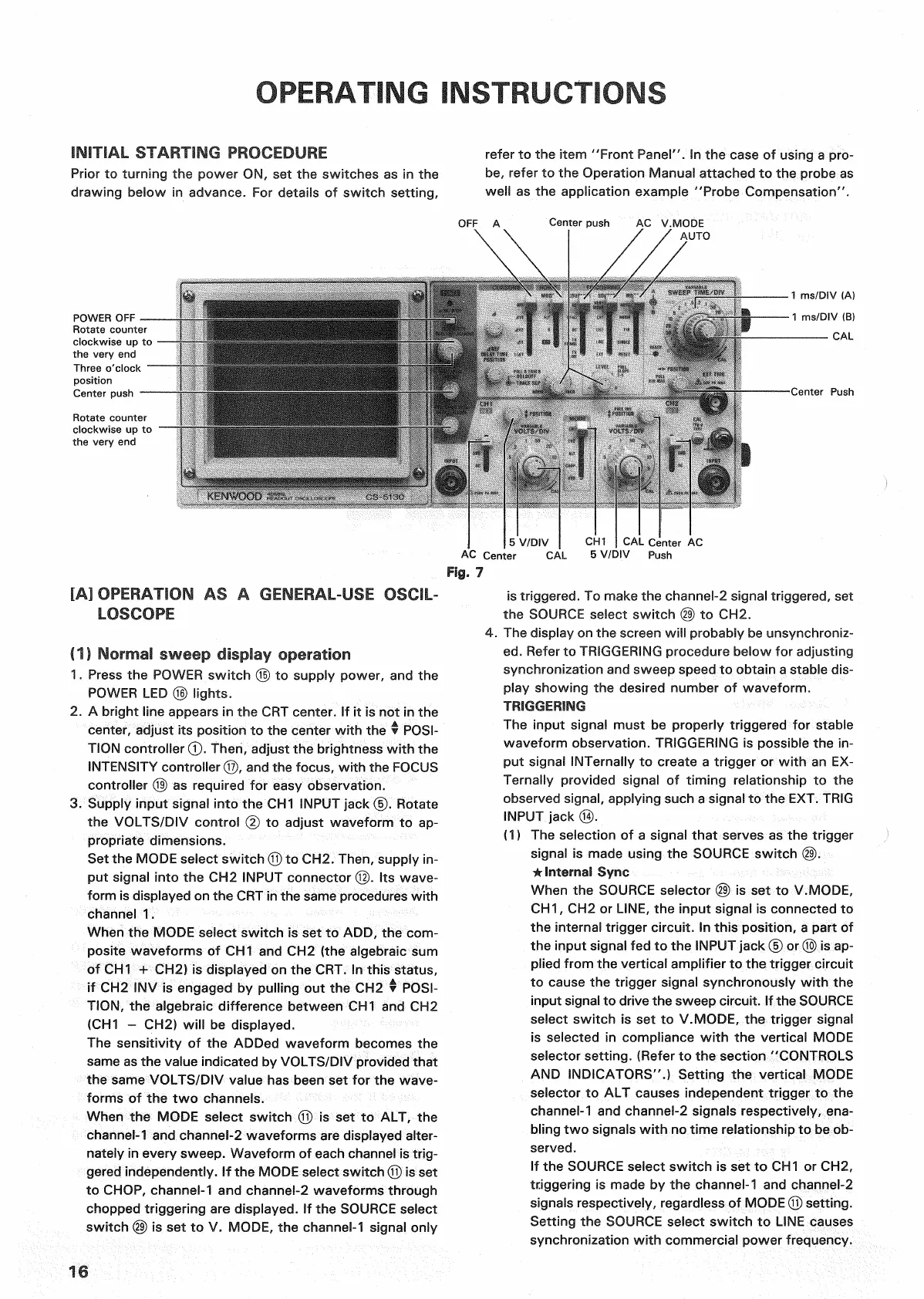
Prior to
turning
the power ON, set the switches as in the
drawing below in advance. For details of switch setting,
refer to the
item
"Front
Panel".
In the
case
of using a pro-
be,
refer to the Operation Manual attached to the probe as
well as the application example "Probe Compensation".
POWER
OFF —
Rotate counter
clockwise
up to
the very end
Three o'clock
position
Center
push
Rotate counter
clockwise
up to
the
very
end
Fig.
7
[A] OPERATION AS A
GENERAL-USE OSCIL-
LOSCOPE
(1) Normal sweep display operation
1.
Press
the
POWER
switch © to supply power, and the
POWER
LED © lights.
2.
A
bright
line appears in the CRT center. If it is not in the
center, adjust its
position
to the center
with
the •
POSI-
TION
controller
(T).
Then,
adjust the brightness
with
the
INTENSITY
controller®, and the focus,
with
the
FOCUS
controller @ as required for
easy
observation.
3.
Supply
input
signal
into
the CH1
INPUT
jack ©. Rotate
the
VOLTS/DIV
control
© to adjust waveform to ap-
propriate dimensions.
Set
the MODE select switch © to CH2.
Then,
supply in-
put signal
into
the CH2
INPUT
connector ©. Its wave-
form
is displayed on the
CRT
in the same procedures
with
channel 1.
When the MODE select switch is set to ADD, the com-
posite waveforms of CH1 and CH2 (the algebraic sum
of CH1 + CH2) is displayed on the
CRT.
In this status,
if CH2 INV is engaged by
pulling
out the CH2 •
POSI-
TION,
the algebraic difference between CH1 and CH2
(CH1
- CH2)
will
be displayed.
The
sensitivity of the ADDed waveform becomes the
same
as the value indicated by
VOLTS/DIV
provided
that
the same
VOLTS/DIV
value has been set for the wave-
forms of the two channels.
When the MODE select switch © is set to ALT, the
channel-1 and channel-2 waveforms are displayed alter-
nately in every sweep. Waveform of each channel is trig-
gered independently. If the MODE select switch © is set
to
CHOP,
channel-1 and channel-2 waveforms
through
chopped
triggering
are displayed. If the
SOURCE
select
switch (§) is set to V. MODE, the channel-1 signal only
is
triggered. To make the channel-2 signal triggered, set
the
SOURCE
select switch
(29)
to CH2.
4.
The display on the screen
will
probably be unsynchroniz-
ed.
Refer
to
TRIGGERING
procedure below for adjusting
synchronization and sweep speed to
obtain
a stable dis-
play showing the desired number of waveform.
TRIGGERING
The
input
signal must be properly
triggered
for stable
waveform observation.
TRIGGERING
is possible the in-
put signal INTernally to create a
trigger
or
with
an EX-
Ternally
provided signal of
timing
relationship to the
observed signal, applying such a signal to the
EXT.
TRIG
INPUT
jack ®.
(1)
The selection of a signal
that
serves
as the
trigger
signal is made using the
SOURCE
switch @.
* Internal
Sync
When the
SOURCE
selector
(29)
is set to V.MODE,
CH1,
CH2 or
LINE,
the
input
signal is connected to
the internal
trigger
circuit. In this position, a part of
the
input
signal fed to the
INPUT
jack © or® is ap-
plied
from
the vertical amplifier to the
trigger
circuit
to
cause
the
trigger
signal synchronously
with
the
input
signal to drive the sweep circuit. If the
SOURCE
select
switch is set to V.MODE, the
trigger
signal
is
selected in compliance
with
the vertical MODE
selector setting.
(Refer
to the section
"CONTROLS
AND
INDICATORS".)
Setting the vertical MODE
selector to ALT
causes
independent
trigger
to the
channel-1 and channel-2 signals respectively,
ena-
bling
two signals
with
no
time
relationship to be ob-
served.
If the
SOURCE
select switch is set to CH1 or CH2,
triggering
is made by the channel-1 and channel-2
signals
respectively, regardless of MODE © setting.
Setting the
SOURCE
select switch to
LINE
causes
synchronization
with
commercial power frequency.
16

 Loading...


