[EXAMPLE]
For
the example, when the horizontal distance between two
signals
is 4.4 divisions. The
SWEEP
TIME/DIV is 0.2
(ms/div).
(See Fig. 26)
Substituting the given value:
Time
= 4.4 (div) x0.2 (ms/div) = 0.88 ms
(2) Cursor measurement (CS-5130 only)
1.
In the same way as the ordinary measurement, adjust
waveforms to be measured to an easy-to-observe
position.
2.
Set the cursor mode to A T.
3.
Adjust the A
REF
cursor to the
left
point
time
difference
between which is to be measured, and the A cursor to
the
right.
4.
Measured value is displayed in the upper
right
part on
the screen.
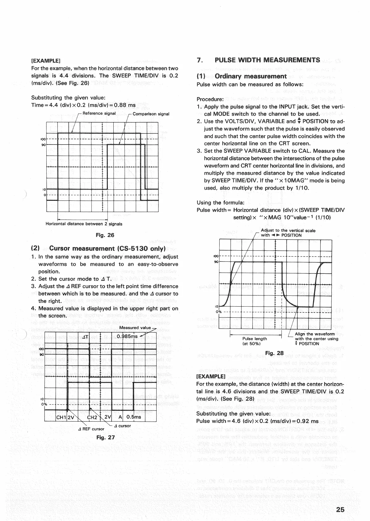
7.
PULSE
WIDTH
MEASUREMENTS
(11 Ordinary measurement
Pulse
width
can be measured as follows:
Procedure:
1.
Apply the pulse signal to the INPUT jack. Set the verti-
cal
MODE switch to the channel to be used.
2.
Use the
VOLTS/DIV,
VARIABLE
and •
POSITION
to ad-
just the waveform such
that
the pulse is easily observed
and such
that
the center pulse
width
coincides
with
the
center horizontal line on the CRT screen.
3.
Set the
SWEEP
VARIABLE
switch to CAL. Measure the
horizontal distance between the intersections of the pulse
waveform and
CRT
center horizontal line in divisions, and
multiply
the measured distance by the value indicated
by
SWEEP
TIME/DIV.
If the " x 10MAG" mode is being
used,
also
multiply
the
product
by 1/10.
Using the formula:
Pulse
width
= Horizontal distance (div) x
(SWEEP
TIME/DIV
setting) x "xMAG 10"value-
1
(1/10)
Adjust
to the vertical
scale
with
• POSITION
Fig.
28
[EXAMPLE]
For
the example, the distance (width) at the center horizon-
tal line is 4.6 divisions and the
SWEEP
TIME/DIV is 0.2
(ms/div).
(See Fig. 28)
Substituting the given value:
Pulse
width
= 4.6 (div) x 0.2 (ms/div) = 0.92 ms
25
Reference
signal
Comparison
signal
Pulse
length
(at 50%)
Align the waveform
with
the center using
§ POSITION
Horizontal distance between 2 signals
Fig.
26
Measured value
REF
cursor
i
cursor
Fig.
27

 Loading...


