5. TIME MEASUREMENTS
11!
Ordinary measurement
Time
between two points on a wave can be measured
from
the
SWEET
TIME/DIV
value and horizontal distance between
two points.
Procedure:
1.
Apply the signal to be measured to the INPUT jack. Set
the vertical MODE to the channel to be used. Set the AC-
GND-DC
to DC, adjusting
VOLTS/DIV
and
SWEEP
TIME/DIV
for a normal display. Set the
VARIABLE
con-
trol
to CAL position.
2.
POSITION
control
to set this
point
at the intersec-
tion
of any vertical graduation line. Using the T
POSI-
TION
control, set one of the points to be used as a
reference to coincide
with
the horizontal centerline.
3.
Measure the horizontal distance between the two points.
Multiply
this by the setting of the
SWEEP
TIME/DIV con-
trol
to
obtain
the
time
between the two points. If horizon-
tal " x 10 MAG " is used,
multiply
this further by
1
/10.
Using the formula:
Time
= Horizontal distance (div) x
(SWEEP
TIME/DIV set-
ting) x"x 10 MAG" value-
1
(1/10)
Adjust
to the vertical
scale
with
** ** POSITION
Horizontal distance
between 2 signals
Adjust
to horizontal
center line
with
T
POSITION
Fig.
24
[EXAMPLE]
For
the example, the horizontal distance between the two
points is 5.4 divisions.
If the
SWEEP
TIME/DIV is 0.2 ms/div we calculate. (See Fig.
24)
Substituting the given value:
Time
= 5.4 (div) x0.2 (ms/div) = 1.08 ms
|2)
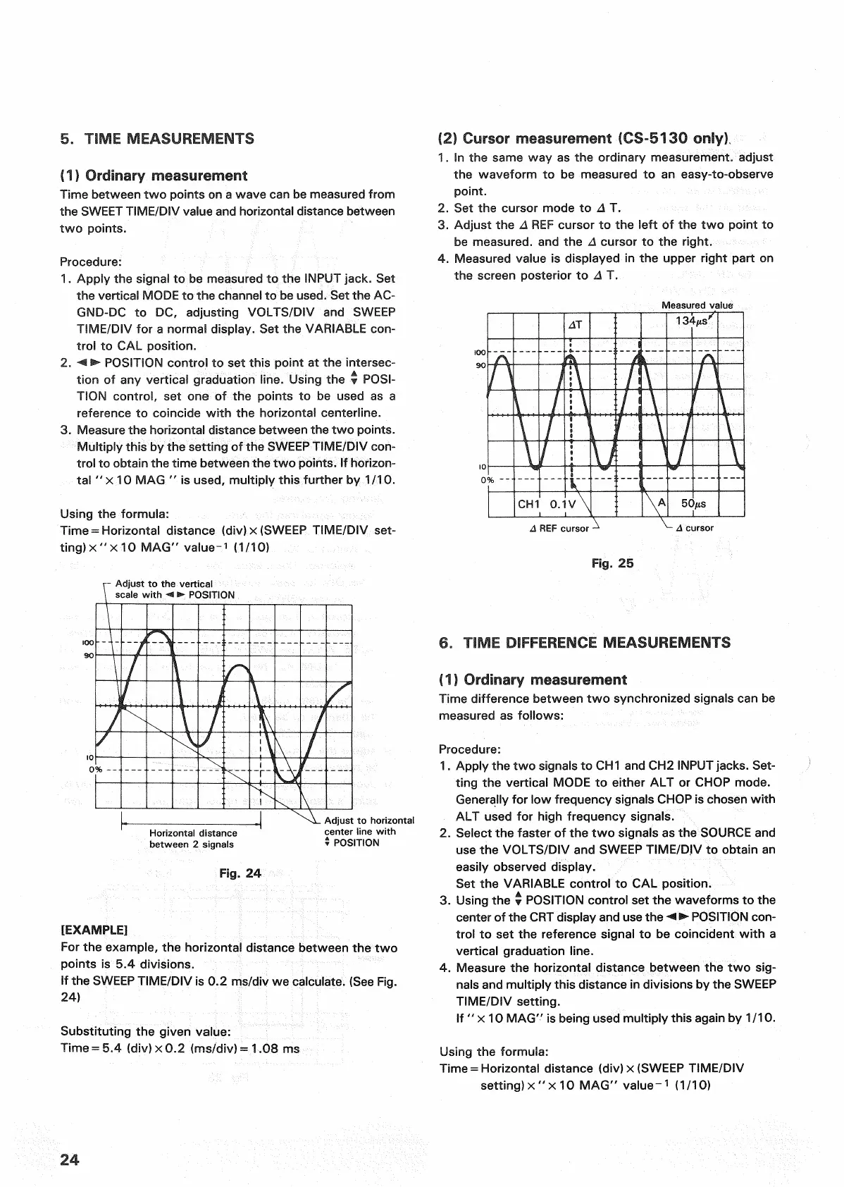
Cursor measurement (CS-5130 only).
1.
In the same way as the ordinary measurement, adjust
the waveform to be measured to an easy-to-observe
point.
2.
Set the cursor mode to A T.
3.
Adjust the A
REF
cursor to the
left
of the two
point
to
be measured, and the A cursor to the
right.
4.
Measured value is displayed in the upper
right
part on
the screen posterior to A T.
Measured value
REF
cursor
cursor
Fig.
25
6. TIME
DIFFERENCE
MEASUREMENTS
(1) Ordinary measurement
Time
difference between two synchronized signals can be
measured
as follows:
Procedure:
1.
Apply the two signals to CH1 and CH2
INPUT
jacks.
Set-
ting
the vertical MODE to either ALT or
CHOP
mode.
Generally
for low frequency signals
CHOP
is chosen
with
ALT
used for
high
frequency signals.
2.
Select the faster of the two signals as the
SOURCE
and
use
the
VOLTS/DIV
and
SWEEP
TIME/DIV to
obtain
an
easily
observed display.
Set
the
VARIABLE
control
to CAL position.
3.
Using the •
POSITION
control
set the waveforms to the
center of the
CRT
display and use the •< •
POSITION
con-
trol
to set the reference signal to be coincident
with
a
vertical graduation line.
4.
Measure the horizontal distance between the two
sig-
nals
and
multiply
this distance in divisions by the
SWEEP
TIME/DIV
setting.
If "x 10 MAG" is being used
multiply
this again by 1/10.
Using the formula:
Time
= Horizontal distance (div) x
(SWEEP
TIME/DIV
setting) x " x 10 MAG" value-
1
(1/10)
24

 Loading...


