9. PHASE
DIFFERENCE
MEASUREMENTS
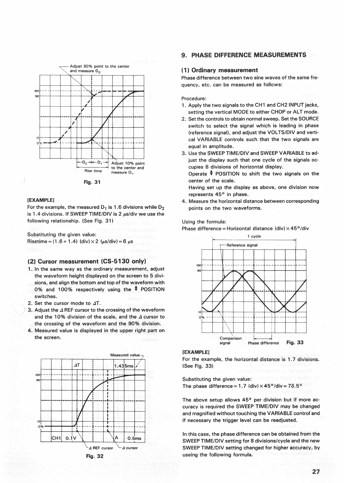
Adjust
90% point to the center
and measure D
2
.
Rise
time
Fig.
31
[EXAMPLE]
For
the example, the measured D-| is 1.6 divisions while D2
is
1.4 divisions. If
SWEEP
TIME/DIV is 2 /ts/div we use the
following
relationship. (See Fig. 31)
Substituting the given value:
Risetime
= (1.6+1.4) (div)x2 (^ts/div) = 6
jxs
(2) Cursor measurement (CS-5130 only)
1.
In the same way as the ordinary measurement, adjust
the waveform height displayed on the screen to 5 divi-
sions,
and align the
bottom
and top of the waveform
with
0%
and 100% respectively using the •
POSITION
switches.
2.
Set the cursor mode to AT.
3.
Adjust the A
REF
cursor to the crossing of the waveform
and the 10% division of the
scale,
and the A cursor to
the crossing of the waveform and the 90% division.
4.
Measured value is displayed in the upper
right
part on
the screen.
f
1)
Ordinary, measurement
Phase
difference between two sine waves of the same fre-
quency, etc. can be measured as follows:
Procedure:
1.
Apply the two signals to the CH
1
and CH2
INPUT
jacks,
setting the vertical MODE to either
CHOP
or ALT mode.
2.
Set the controls to
obtain
normal sweep. Set the
SOURCE
switch to select the signal which is leading in phase
(reference
signal), and adjust the
VOLTS/DIV
and verti-
cal
VARIABLE
controls such
that
the two signals are
equal in amplitude.
3.
Use the
SWEEP
TIME/DIV and
SWEEP
VARIABLE
to ad-
just the display such
that
one cycle of the signals oc-
cupies
8 divisions of horizontal display.
Operate •
POSITION
to shift the two signals on the
center of the
scale.
Having set up the display as above, one division now
represents
45° in phase.
4.
Measure the horizontal distance between corresponding
points on the two waveforms.
Using the formula:
Phase
difference = Horizontal distance (div) x 45°/div
cursor
[EXAMPLE]
For
the example, the horizontal distance is 1.7 divisions.
(See
Fig. 33)
Substituting the given value:
The
phase difference = 1.7 (div)x45°/div = 73.5°
The
above setup allows 45° per division but if more ac-
curacy
is required the
SWEEP
TIME/DIV may be changed
and magnified
without
touching the
VARIABLE
control
and
if necessary the
trigger
level can be readjusted.
In this
case,
the phase difference can be obtained
from
the
SWEEP
TIME/DIV
setting for 8 divisions/cycle and the new
SWEEP
TIME/DIV setting changed for higher accuracy, by
useing the
following
formula.
27
Adjust
10% point
to the center and
measure
D,.
1
cycle
Reference
signal
Comparison
signal
Phase
difference
Fig.
33
Measured value
REF
cursor
Fig.
32

 Loading...


