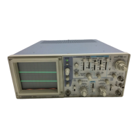
CONTROLS
AND INDICATORS
FRONT
PANEL
Fig.
2
© CH1 | POSITION Control
Rotation adjusts vertical position of
CH1
waveform on
the
screen.
In X-Y operation,
rotation
adjusts vertical
position of display.
@
CH1 VOLTS/DIV Control
Vertical
attenuator for channel 1. Provides step adjust-
ment of vertical sensitivity in 1-2-5 sequence.
VARI-
ABLE
control is turned to the CAL position, the
calibrated vertical sensitivity is obtained. In X-Y opera-
tion, this control
serves
as the attenuator for
Y-axis.
© CH1
VARIABLE
Control
Rotation provides fine control of channel 1 vertical
sen-
sitivity. In the fully clockwise
(CAL)
position, the verti-
cal
attenuator is calibrated. In X-Y operation, this control
serves
as the
Y-axis
attenuation fine adjustment.
@
CH1 AC-GND-DC Switch
This
switch is the CH1 vertical
axis
coupling mode
selector,
for X-Y operation, the
Y-axis
coupling mode
control.
AC:
AC
input
coupling
with
blocking of any DC
sig-
nal
component.
GND:
Vertical amplifier is disconnected
from
the in-
put signal and connected to ground.
This
mode
is
useful in determining the zero reference.
DC:
DC coupling,
with
both
the DC and AC com-
ponents of the
input
signal displayed on the
CRT.
© CH1 INPUT jack
Vertical
input
for channel 1 trace in normal sweep oper-
ation.
Y-axis
input
for X-Y operation.
© $ CH2 POSITION/PULL
INVert
Control
• CH2
POSITION:
Rotation adjusts vertical position of channel 2
trace.
INV:
Push-pull switch selects channel 2 signal in-
verted
(PULL
INV) when pulled out.
(Hereafter
PULL
INV is described as CH2 INV.)
© CH2 VOLTS/DIV Control
Vertical
attenuator for CH2. Provides the same func-
tion
as
VOLTS/DIV
Control © for
CH1.
In X-Y opera-
tion, the control
serves
as the
X-axis
attenuator.
® CH2
VARIABLE
Control
Rotation provides fine control of channel 2 vertical
sen-
sitivity.
Provides
the same function as
VARIABLE
Control ® for
CH1.
In X-Y operation, this control
serves
for
X-axis
at-
tenuation fine adjustment.
© CH2 AC-GND-DC Switch
Three-position lever switch which operates as follows:
AC:
Blocks DC component of channel 2
input
signal.
GND:
Opens signal path and grounds
input
to vertical
amplifier.
This
provides a zero-signal base line,
the position of which can be used as a reference
when performing DC measurements.
DC:
Direct
input
of AC and DC component of chan-
nel 2
input
signal.
9

 Loading...