12)
CURSOR
measurement
1)
Make the GND luminescent line be displayed by means
of ordinary procedures 1) and 2).
2)
Set the cursor mode to A V1 or A V2 in accordance
with
the channel to be used.
3)
Adjust the A
REF
cursor (reference line) to the GND lu-
minescent line.
4)
Set the AC-GND-DC switch to DC.
5)
Adjust the A cursor to a
point
to be measured.
6)
Measured value is displayed in the upper
right
part on
the screen.
If the attached probe
PC-33
is used, measured value in-
cluding the attenuation
ratio
is displayed. If a probe in-
compatible
with
the readout
function
is used, measured
value
is
multiplied
by the attenuation ratio.
Lowering of the A cursor below the A
REF
cursor indi-
cates
negative voltage, displaying " - ".
Measured value
Fig.
18
2.
MEASUREMENT OF THE
VOLTAGE
BETWEEN
TWO POINTS ON A WAVEFORM
ID Ordinary measurement
This
technique can be used to measure peak-to-peak
voltages.
1.
Apply the signal to be measured to the INPUT jack. Set
the vertical MODE to the channel to be used. Set the ver-
tical MODE to the channel to be used. Set the AC-GND-
DC
to AC, adjusting
VOLTS/DIV
and
SWEEP
TIME/DIV
for a normal display. Set the
VARIABLE
control
to CAL
position.
2.
Using the T
POSITION
control, adjust the waveform po-
sition such
that
one of the two points falls on a CRT
graduation line and
that
the other is visible on the dis-
play screen.
3.
Using the
POSITION
control, adjust the second
point
to coincide
with
the center vertical graduation line.
4.
Measure the vertical distance between the two points
and
multiply
this by the setting of the
VOLTS/DIV
control.
When a 10:1 probe is used, further
multiply
the value
by 10.
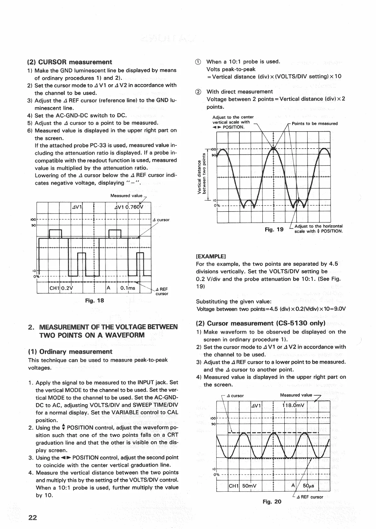
© When a 10:1 probe is used.
Volts peak-to-peak
=
Vertical distance (div) x
(VOLTS/DIV
setting) x 10
(2)
With
direct measurement
Voltage between 2 points = Vertical distance (div) x 2
points.
Adjust
to the center
vertical
scale
with
-+ • POSITION.
Points
to be measured
[EXAMPLE]
For
the example, the two points are separated by 4.5
divisions vertically. Set the
VOLTS/DIV
setting be
0.2 V/div and the probe attenuation be 10:1. (See Fig.
19)
Substituting the given value:
Voltage between two points=4.5 (div) x 0.2(V/div) x 10=9.0V
|2!
Cursor measurement (CS-5130 only)
1)
Make waveform to be observed be displayed on the
screen
in ordinary procedure 1).
2)
Set the cursor mode to A V1 or A V2 in accordance
with
the channel to be used.
3)
Adjust the A
REF
cursor to a lower
point
to be measured,
and the A cursor to another
point.
4)
Measured value is displayed in the upper
right
part on
the screen.
A cursor
Measured value
Z
Fig.
20
A REF cursor
22
Vertical
distance
between
two
points
Fig.
19
Adjust
to the horizontal
scale
with
± POSITION.
cursor
._
REF
cursor

 Loading...


